This article covers different resistance measurement methods along with their circuit diagrams such as Volt-Ammeter Testing, Wheatstone Bridge, Generator & Battery powered Insulation Tester, Bridge Megger, and Fault Loop Impedance Tester.
Parallel and series ohmmeter circuits are used as a means of determining values of resistance. Both circuits, however, have limits beyond which their accuracy is questionable.
Parallel ohmmeter circuits perform better than series circuits for low values of resistance, but as resistance values get still lower, errors can creep in. The resistance of the terminal connections and that of the leads connecting the resistor under test begin to have an appreciable effect.
Similarly, the series ohmmeter circuit outperforms the parallel circuit for higher values of resistance, but as resistance values increase, the current flowing through the resistor and the meter decreases. A point is eventually reached where the meter is no longer able to indicate a value accurately.
Volt-Ammeter Testing
For most purposes a resistance measurement can be obtained with sufficient accuracy by passing current through the resistor under test and at the same time measuring both the current through and the voltage across it. The resistance is then calculated by applying Ohm’s law.
For greater accuracy, care must be taken in the connection of the circuit. Figure 1 shows two possible circuits.
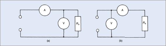
Figure 1 Volt-ammeter circuits for determining an unknown resistance
In Figure 1(a) the ammeter will measure the current flowing through the voltmeter as well as that through the resistor. If the resistor has a comparatively low value of resistance when compared to the voltmeter resistance, the discrepancy in ammeter reading can be ignored. For example, if the current flowing through the resistor is, say, 1 A and the current flowing through the voltmeter is 50 μA, the ammeter is unable to discriminate between readings of 1 A and 1.00005 A.
On the other hand, if the current flowing through the resistor is 100 μA, a suitable ammeter would read a current flow of 150 μA (IR + Im) and an error of appreciable percentage would result. Figure 1(a) is therefore a more suitable circuit for measuring low resistance values.
Figure 1(b) shows the voltmeter connected across the supply source. The ammeter now reads only the current flowing through the resistor. With this circuit, the voltmeter reads the supply source or the sum of the voltage drops across the resistor and the ammeter in series, that is, V = Vm + VR.
For accuracy, with this circuit the voltage across the resistor must be far greater than the voltage drop across the ammeter. Assuming that the ammeter has a 50 μA movement and the internal resistance is 5 kΩ, the voltage drop across the meter is V = IR = 50 μA × 5000 = 0.25 V.
For best results the potential difference (PD) across the resistor has to be many times this value, that is, a value around 60 V or more. For lower voltage values the error increases considerably.
These methods for obtaining resistance values have serious limitations as regards both accuracy and versatility. Two meters are employed and this means that the possibilities for introducing errors are greatly increased. Voltages and currents also have to be adjusted to suit resistor and meter ratings.
The diagram in Figure 1(a) is the circuit in general use, provided a good quality analogue multimeter with a high internal impedance is used. Some analogue multimeters have input impedances of 10 MΩ or higher and as a consequence the loading on the circuit is minimal. A good quality digital multimeter can be substituted, provided it is of sufficient accuracy.
Wheatstone Bridge
The Wheatstone bridge circuit was first described by S. H. Christie in 1833. It was virtually ignored until taken up by (Sir) Charles Wheatstone in 1843.
It was first intended for accurate measurement of values of resistance but was adapted and modified to suit many different circuits able to measure other values. Figure 2(a) illustrates the original circuit. It comprises three known resistors and the unknown resistor making up the fourth arm of the bridge.
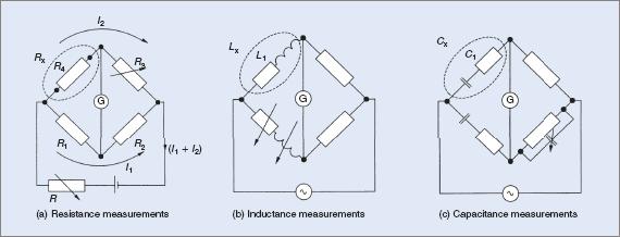
Figure 2 Wheatstone bridge circuit diagrams
Figure 2(b) shows one modification for measuring inductance and Figure 2(c) is another modification for measuring capacitance. There are many variations of these three circuits, usually named after the people who developed them. All are based on the original bridge circuit.
With good quality equipment the bridge circuit will measure accurately down to 0.01 Ω. For the standard bridge circuit this is about its lower limit. Further modifications to the original circuit enable the bridge to be used to measure accurately down to 0.001 Ω.
Altering the ratios of resistors R1 and R2 in the arms of the bridge enables resistances of much higher or lower values to be measured. The value of voltage used to supply the bridge is immaterial because the circuit is adjusted correctly when the meter indicates a null, that is, when the meter pointer remains stationary on zero. The bridge is then said to be balanced.
High or lower values of voltage mean only that the higher or lower values of current flow through the bridge and make the meter susceptible to possible overload and damage in the unbalanced state. The meter used in the circuit is usually a sensitive moving-coil meter with a center-zero scale. It is sometimes referred to as a galvanometer.
When the bridge is balanced, the voltage drop across the unknown resistor (Rx in Figure 2(a)) is equal to the voltage drop across resistor R1. This also means that the potentials across resistors R2 and R3 are also equal to each other, that is:
$$\textrm{ At null: } I_{1}R_{1}=I_{2}R_{x}$$
$$\textrm{ similarly: } I_{1}R_{2}=I_{2}R_{3}$$
$$\textrm{Dividing (1) by (2)} I_{1}R_{1}/I_{1}R_{2}=I_{2}R_{x}/I_{2}R_{3}$$
$$\textrm{Then, cancelling the I’s the equation becomes:}$$
$$R_{1}/R_{2}=R_{x}/R_{3}$$
$$R_{x}=\frac{R_{1}.R_{3}}{R_{2}}$$
In practice, resistance arms R1 and R2 are usually made adjustable in ratios of 0.1, 1, 10, 100 and 1000. This approach enables the bridge circuit’s range to be expanded to cover a wider range of values.
It also means that when using the bridge to measure resistances, multiplying factors might have to be taken into account for calculation purposes.
In practical Wheatstone bridges the actual values of R1 and R2 might not be known. It is usual to have them labelled as a switch, with its position indicating the ratio between them. Rx is read directly off the values set by the adjustable resistor R3. The value obtained by R3 at the null position is then multiplied or divided by the indicated ratio.
The following two examples illustrate the calculations involved in using a bridge circuit.
Example 1
The resistances on a bridge read R1 = 10 k Ω, R2 = 1 k Ω and R3 = 3.95 k Ω. Find the value of the resistance being measured.
$$R_{x}=\frac{R_{1}.R_{3}}{R_{2}}=10000\times 3920/1000=39.20K\Omega$$
Example 2
The resistances on a bridge read R1 = 100 Ω, R2 = 1000 Ω, and R3 = 68.4 Ω. Find the value of the resistance being measured.
$$R_{x}=\frac{R_{1}.R_{3}}{R_{2}}=100\times 68.4/1000=6.84K\Omega$$
Insulation Resistance
In practical terms a battery-operated circuit as described in Example 2 is neither convenient, accurate nor practical for measuring very high values of resistance.
A high voltage is required to ensure that a reasonable amount of current is able to flow in the circuit being tested. This is necessary to enable a meter to be able to give a more positive indication.
Australian Standards specify minimum voltages for testing circuits. As an approximation it is about double the operating voltage of the circuit. That is, on a 240 V circuit, the specified test voltage is 500 V. If testing between phases, 1000 V should be applied.
Probably the original maker of an instrument for tests of this nature was an English firm known today as Meggar Instruments Ltd. The original name was Evershed and Vignoles and the trade name for the unit was ‘Meggar’. The trade name has become a generic term and is almost universally used to describe instruments of this type. It should be noted that other firms manufacture similar test instruments and all should be known as insulation testers.
There are two general arrangements for obtaining the necessary voltages; one a hand-cranked generator, the other dry cells and an electronic circuit.
Generator-Powered Insulation Testers
To make the instrument truly portable there has to be an inbuilt power source. This was achieved in the original meggar with a generator cranked by hand. Earlier models used a DC generator, while later models took advantage of the strength of modern magnets rotating inside a coil to produce an alternating voltage. The resulting AC was converted to DC internally and used to operate the instrument. The circuit of a DC generator and insulation tester is shown in Figure 3.

Figure 3 Insulation-test meter circuit diagram
Analysis of the circuit will show that it is a variation of the series ohmmeter circuit, since the generator, deflecting coil, deflecting coil resistor and the resistance being tested are all in series.
The moving coil with attached pointer is actually two coils fixed at right angles to each other. The second coil is connected in series with another resistor directly across the voltage source powering the instrument. This second coil acts in place of a return spring to return the pointer to zero. There is no other restraining spring against which torque must be exerted.
The final position of the coil depends on the relative amounts of current flowing in each coil. One current is governed by the voltage supply and the other by the current flowing through the circuit being tested. Normal measuring ranges are 0–200 MΩ, with a fair degree of accuracy.
Battery-powered insulation testers
Many modern instruments made by other manufacturers use a bank of dry cells to energize an electronic circuit. The output from this circuit is high-voltage, high-frequency AC, which is then rectified and used to operate the instrument.
The complete unit is usually much smaller and lighter than a generator-powered instrument but care must be taken to ensure that the batteries are in good condition for satisfactory operation of the tester.
Once a suitable value of DC voltage is obtained, the operation of the unit is much the same as the generator-powered unit. The normal operating resistance range is 0–200 MΩ. Standard models are available in voltages of 100 V, 250 V, 500 V or 1000 V and accuracy is equivalent to that of the meggar.
Because the instruments are battery powered it is normal for one of the test probes to include a switch that must be held down while the instrument is actually in operation. On release of the probe the battery is disconnected.
The voltage in modern insulation testers is generated by an internal switched power supply, or inverter circuit, capable of generating these high voltages from a set of 1.5 V batteries.
Later models of the battery-powered insulation testers have digital readouts. The readout is supplied directly with power from the batteries.
As there is such a variety of these types of testers, the use of a particular type of instrument is generally a personal choice of the technician, and whether they choose analogue or digital.
Bridge Meggers
Several variations of the basic meggar circuit have been produced. One version includes a built-in bridge circuit for measurement of lower values of resistance. The instrument is much larger, heavier and more expensive than the meggar described previously. A circuit of a bridge meggar is shown in Figure 4.
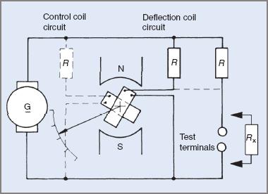
Figure 4 Basic bridge meggar circuit diagram
It can be seen that adjustable resistors are connected into the circuit. This is achieved with the aid of the switches on the side of the instrument housing (see Figure 5). On the top surface are the four rotary switches, which operate the resistance box component of the bridge-measuring circuit.
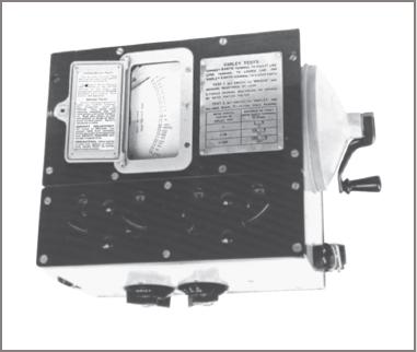
Figure 5 A 500 V bridge meggar
When used as an insulation tester the bridge megger is a direct-reading series ohmmeter for high resistance values. When switched to the bridge configuration the circuit has to be balanced by adjusting the rotary switches. The infinity end of the scale is taken as the null or balanced position. In the bridge-balanced position the pointer rests directly above the infinity symbol.
One of the major applications of a bridge megger instrument is the location of cable faults. The resistance between the ends of cables and the fault can be accurately measured and, by calculation, the distance to the location of the fault can be obtained. The circuit connection most often used has been given the name ‘Varley loop’ after the man who proposed the method.
More modern instruments, called TDR meters, are now being used to locate cable faults in either communication cable or power cables. They typically identify open circuits, short circuits, and crossed pairs and so on.
Continuity Testing
Another variation of the megger circuit is intended for testing the continuity and resistance of conductors in an installation. While the standard megger operates as a series ohmmeter for resistance ranges of 0–100 MΩ, 0–200 MΩ or 0–550 MΩ in some instances, the continuity tester operates like a parallel-connected ohmmeter. Its normal resistance range is dependent upon the manufacturer. The continuity part of a megger is typically used for earthing continuity tests.
Hi-Pot Testing
Just as the Standards require a higher current for low ohms tests, insulation tests under Australian and International standards are often performed at 1500 V, or up to 4500 V. Insulation, clearance and creep age distances are expected to be sufficient to prevent 1 mA from flowing even at such high voltages.
Care in the Use of Meggers
A 500 V megger can cause an electric shock unless care is taken when using it. Inadvertent contact with the test leads can give rise to an unpleasant electric shock. Similarly, other technicians handling the same conductors being tested can be affected.
Underground cables are often tested with higher voltages. Meggers generating 3000 V are commonly used for the purpose. Apart from direct electric shocks from the instrument, there is an additional danger created by the capacitance effects of the cable. This applies particularly to armored or metal-sheathed underground cables as well as MIMS cables.
The capacitance created by the method of construction of the cable enables an electric charge to be stored on the cable. The charge is created from the DC of the megger and generally exists between the conductor and the armored metal sheath protecting the cable.
Because the actual capacitance can vary widely from cable to cable, it is usually expressed in microfarads per unit length. One typical cable has a capacitance of approximately 0.2 μF/300 m. Others may have higher or lower capacitances.
At 3000 V, this capacitance relates to an energy storage of around 9 J. This quantity of charge at this voltage can cause enough of a shock to immobilize a technician for a time. Sometimes medical attention is needed.
On an aerodrome, for example, there can be many kilometers of underground cable, so the scope for an electric shock is considerable. Even with a comparatively short length of underground cable this equates to an energy content at a voltage that can kill.
This is why it is a good idea to discharge the cable after testing. Typically electricians will do this by shorting a screwdriver or something similar across the sheath and conductor. However, care should be taken in doing this as it may present other risk hazards.
Before relying on readings taken by a megger on an installation that contains capacitance, the operator should ensure the installation is charged up to the voltage of the megger. This is generally done by extended testing on any one conductor for a period of time. The meter reading usually indicates that this has been achieved when the reading stabilizes at one value.
For example, when reading the resistance of one conductor in an underground cable to its sheath, the megger may show a reading which indicates a low resistance path to earth. On persisting with the test the megger reading will generally climb to a much higher—and more satisfactory—reading.
Fault Loop Impedance Testers
Under existing self-regulatory conditions for electrical workers, the worker can be expected to check the fault loop conditions for an installation. The fault loop is the path from the installation’s main earth back to the supply point where the main neutral is also grounded.
Fault loop impedance testers are designed to give an indication of the impedance of that path.
The tester itself may be a combination of megger, continuity tester and other functions such as testing the operation and effectiveness of any residual current device in that installation.
The loop test places a known resistor between one phase of the installation and measures both the no-fault voltage and the voltage under simulated fault conditions. This is then processed in the instrument and provides a reading in ohms impedance for the loop back to the supply via the earth return.
For safety and residual current devices a good earth return is generally considered a must. Particularly with the later electronic devices, the testing of the loop impedance can cause tripping at least and a possibility of damage to the device itself. In either case an interruption to the supply service can vary from a minor nuisance in domestic cases to a major problem involving safety in an industrial installation.
Figure 6 shows a typical fault loop impedance tester. Note, this instrument also has the ability to test for prospective fault levels within an installation. Typically these testers have two types of leads; one with a male plug for testing socket outlets and one with alligator type clamps for testing electrical equipment and apparatus.
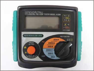
Figure 6 Fault loop tester
Resistance Measurement Methods Key Takeaways
Understanding and accurately measuring electrical resistance is fundamental to designing, troubleshooting, and maintaining reliable electrical systems. Each method discussed—whether it’s the basic volt-ammeter approach, the precision of the Wheatstone bridge, or the high-voltage testing capabilities of insulation testers—serves a unique and critical role depending on the resistance range and application needs. For example, volt-ammeter circuits are essential for general-purpose resistance checks, while Wheatstone bridges offer precise measurements necessary in calibration and component testing. Insulation testers and bridge meggers are vital in ensuring the safety and integrity of high-voltage installations by identifying potential insulation failures.