The article discusses various DC motor starting methods, including manual and automatic starters, their circuit diagrams, and the importance of controlling starting current to prevent damage. It covers key concepts such as back EMF starting, solid-state controllers, and acceleration control while explaining the effects of direct-on-line starting and the role of resistances in regulating motor performance.
we have covered DC motor starting methods along with their circuit diagrams in details:
Three-terminal faceplate starters
Automatic DC Motor Starters
Automatic Acceleration Control
Back EMF Starting
Solid State Controllers
Direct current (DC) motors up to 1.5 kW can be started directly on line but as this allows excessive armature currents to flow it can cause burning of both the commutator and the brushes. Smaller armatures, due to their low inertia, can sometimes be started direct on line but larger ones cannot.
A typical 200 V 5 kW DC motor has an armature resistance of about 0.3 Ω. From Ohm’s law it can be seen that the starting current is many hundreds of amperes:
$$I=V/R=200/0.3=667A$$
This high current drain is a direct result of the armature not rotating and being able to generate a back EMF. A general guide is to limit the maximum starting current to about two or three times full-load current. This Figure, it should be noted, is only a general guide and can be affected by such factors as motor size, duty cycle and type of load.
A DC motor starting on load needs a different type of starter to a motor starting without a load. The starting current can vary from 1.5 to 7 times full-load current.
The only effective means to prevent damage caused by high starting currents is to limit the current by inserting resistance in series with the armature.
The effects of starting a DC motor DOL are:
1. Rapid wear of brushes
2. Burning of the commutator surface
3. Overheating of commutator connections, leading to open circuits in the armature
4. Burning of brush pigtails
5. Flexing of armature windings, leading to chafing of armature windings and short-circuits
6. Shock loads on armature shafts, mounting bolts, drive belts or other transmission components
7. Heavy current surges (transients) on supply source.
Figure 1 illustrates the basic principle for limiting the starting current of a DC motor.
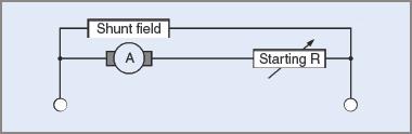
Figure 1 Basic starting circuit diagram for a DC motor
The method applies to all types of connection for DC motors. A resistor capable of being varied is inserted in series with the armature, and full voltage is applied to the shunt field. As the DC motor accelerates, the armature resistance is gradually reduced. It is important that shunt fields be kept at or near full line voltage while the motor is being accelerated up to full speed.
Desirable elements of DC motor starters and starting are:
1. Circuit isolation
2. Over-current protection
3. All series armature resistance in circuit when starting
4. Full line voltage applied to shunt field when starting.
Most starters for DC motors reduce the series resistance in a series of steps, so the armature current rises and falls in a series of steps. Figure 2 shows how the current varies for a DC motor with three reducing steps for the series resistance.
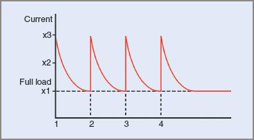
Figure 2 Load current surges during starting sequence
The first current surge occurs when supply is connected to the DC motor. As the motor gradually accelerates, a generated EMF builds up and opposes the applied voltage. Because the difference between generated EMF and applied EMF gradually decreases, the armature current also decreases.
When the line current has reduced to approximately full-load current, the first resistance step is removed from the armature circuit and the current again increases abruptly. This is repeated as the DC motor has further gains in speed until all the resistance is taken out of the armature circuit.
Three-terminal faceplate starters
Manual starters are mainly of the three-terminal faceplate type and are designed for use with shunt or compound DC motors. With minor circuit alterations, they can also be used with series DC motors. A typical circuit is shown in Figure 3.
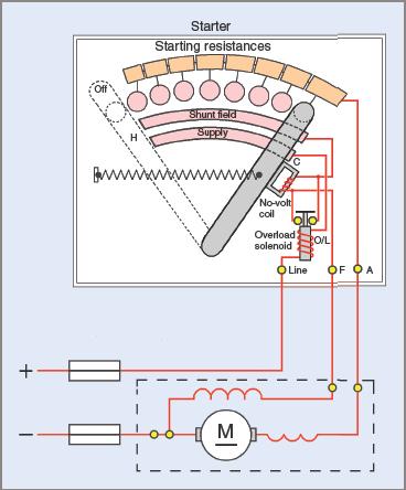
Figure 3 Three-terminal manual DC motor starter circuit diagram
When the spring-loaded starting handle H is moved to the first stud, all the resistance in the starter is inserted in the armature circuit and full voltage is applied to the field.
As the DC motor accelerates, the handle is advanced, removing resistance from the armature circuit. Although this is added to the field circuit, the value of resistance is so low in comparison to the shunt field resistance that its effect can be ignored.
Current flows to the field through a series coil C, which magnetizes an iron core situated so that, when handle H completes the magnetic circuit, it is then held against spring tension in the position where all the armature resistance is shorted out.
The coil C is placed in the circuit to protect the motor and does this in two ways. If the field develops an open circuit, no current flows in the coil and the magnet releases the handle, allowing the spring to return H to the off position before the motor can accelerate to excessively high speeds. (Increased speed of a shunt motor is achieved by weakening the field.) Additionally, should the supply source fail or through some fault decrease to a low voltage, the magnetic strength of C is reduced and the spring again returns H to the off position. The coil C is often called a no-volt release coil.
Some situations, such as overloads on the motor or a faulty starting sequence, can cause the motor to draw an excessive current. To prevent damage to the DC motor, overload protection is usually fitted to DC motor starters.
In Figure 3, a coil of low resistance (O/L) is connected in series with one of the lines. When the current exceeds a preset value, the core is pulled into the coil and an associated pair of contacts shorts out coil C, releasing H and allowing it to return to the off position.
Automatic DC Motor Starters
Although an automatic starter is more expensive than a manual starter, it is electrically superior and has other advantages. A careless or inexperienced operator of a manual system can cause damage to both the starter and the motor if the starter is not used correctly. An automatic starter in good order will, at the press of a button, accelerate the motor up to speed in a starting sequence that can be repeated accurately and consistently.
Other advantages of automatic starters are:
1. Push-Button Control Stations Can Be Located at A Distance from The Starter.
2. Operation Can Be Left to Untrained Personnel.
3. The Push-Button Function Can Be Replaced by A Process Control Mechanism (E.G. Pressure Switches, Float Valves, Moisture Detectors).
In any discussion of automatic starters, it must be appreciated that there are many variations of the basic design, depending on the equipment used, its location and any desired effects of individual starters. In all automatic starters, however, there are two types of circuits: power and control.
The power circuit operates the motor and has the motor current flowing through it. The control circuit works on much smaller currents and operates the switches, contacts, relays and timers necessary for bringing the motor up to speed when required and affording it protection against overloads.
A circuit illustrating the action of an automatic starter for a shunt DC motor is shown in Figure 4. Operation is by push-buttons with the accelerating stages controlled by delayed action relays.
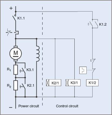
Figure 4 Example of an automatic DC motor starter circuit diagram
The circuit has been divided into two parts with a broken line to distinguish between power and control circuits.
The power circuit is shown to the left of the line, with the motor field, motor armature and the accelerating resistors. The control circuit is to the right of the line, with the pushbuttons, main relays, timing relays and their respective contacts.
Two of the relays are of the delayed-action type. Relay K3/1 has a reaction time of approximately twice that of relay K2/1; for example, 5 seconds for K2/1 and 10 seconds for K3/1.
When the starting button is pressed, relay K1/2 is activated. One of its contacts K1.1 closes and applies full power to the field and also to the armature in series with the starting resistors. The armature current creates torque and the motor commences accelerating. The second contact K1.2 latches the starting button and ensures that power continues to be applied to the motor when the start button is released.
Simultaneously, full voltage is applied to both time-delay relays K2/1 and K3/1. After an elapsed time of, say, 5 seconds, relay K2/1 is activated and contact K2.1 shorts out resistor R2. The reduced resistance in the armature circuit causes an increase in armature current and creates additional torque. This in turn enables further acceleration to a higher speed.
After a longer delay, say 10 seconds, relay K3/1 is activated and closes contact K3.1. This shorts out the remaining resistor in the armature circuit and allows full voltage to be applied to the armature.
The DC motor is protected against overloads by a thermal overload and the use of contactor coils ensures that there is protection against low voltages.
The time taken by a motor to reach operating speed is dependent on the starting torque and the load imposed on the motor.
In the example given above, the stage times are fixed and this may not always be a satisfactory solution to DC motor starting. More effective means might be required.
Automatic Acceleration Control
The nature of the DC motor start, and the way in which the motor accelerates, is governed by the starter itself. When series resistance stages are removed from the armature circuit there are surges in both current and torque. These surges might be unacceptable. For example, if a wrong value of resistor is chosen, a motor might not start on the first stage but will surge violently on a second stage.
The number of resistance stages in the starting procedure also affects the operation of the starter and the motor. A close ratio between maximum and minimum accelerating torques will give a smooth start with minimal surges, but requires many starting stages. A wider ratio, on the other hand, has fewer stages but results in sudden torque and current surges.
To achieve good starting sequences with surges reduced to a minimum, the operation should be taken out of the hands of an operator and made automatic. Then the rates of acceleration will be consistent and reliable.
There are methods for automatic starting control of DC motors that have existed for many years and have proved their reliability. Solid-state technology and more advanced designs of DC motors also make it possible to control the supply of power to the motor over a wide range of operating conditions.
All DC motor starting methods are different ways of starting a motor on a reduced voltage and gradually increasing that voltage until it is on full line voltage. All effective methods control the rate of increase of input current and the accompanying acceleration rates.
Some of these methods are described below.
Definite Time Acceleration
Relays are activated in accordance with strict time intervals. The circuit in Figure 4 is typical of such a method. The method uses timing relays (electrical or mechanical), oil dashpots or electronic timers. No allowance is made for load or motor conditions. For example, a DC motor could be stalled but after a definite time interval, the next stage is activated, that is, less resistance and still more armature current.
Current-Limited Acceleration
This method is suitable for DC motors that have to cope with varying loads where the starting conditions may also vary. The maximum current is predetermined and the starting intervals depend on the magnitude and inertia of the load. Each successive stage is controlled by a contactor that is itself controlled by the previous stage. Auxiliary contacts and coil interlocking methods are used. Current operated relays are used and each relay consists of a set of cylindrical coils designed to carry the armature current. Each will release its iron core at different current levels.
On starting, the first relay will attract its iron core. As the motor accelerates, the armature current will gradually decrease until the relay can no longer hold the core and releases it. Auxiliary contacts are then made.
These activate the next relay in the circuit and at the same time bypass some of the starting resistance in the armature circuit. Acceleration and torque are then increased until the next relay in the sequence goes through the same procedure.
If at any stage the load becomes too much for the motor and the current remains at a high level, the next stage in the starting sequence cannot be initiated.
Back EMF Starting
With back EMF starting, voltage-dependent relay coils are connected in parallel with the armature. As the back EMF generated by the armature rises, the current flowing in the armature falls. This causes the armature voltage to increase until it reaches values that progressively activate relays. These relays remove part of the starting resistance from the armature circuit and the current again increases and repeats the sequence.
If for any reason the DC motor is unable to accelerate to full speed, the current remains high and the relays are unable to reduce the resistance in the armature circuit. The principle of operation is illustrated in Figure 5.
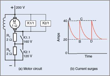
Figure 5 Back EMF DC starter circuit diagram
Assume a supply voltage of 200 V, a full-load current of 20 A, a starting current factor of 2 (40 A), and an armature resistance of 1 Ω. Also, assume that the voltage relays activate at 120 V and 160 V.
If two starting resistors each of 2 Ω were placed in series with the armature, the starting current would be:
$$I=V/R=200/5=40A$$
That is, the current would increase to point A in Figure 5(b) when first switched on.
The voltage distribution across the series armature circuit would be V = IR = 40 × 2 = 80 V across each of the series resistors and 200 − 160 = 40 V across the armature.
As the DC motor accelerates, it generates a back EMF. This opposes the applied voltage and produces a lower net applied voltage and this causes the armature current to decrease.
When the current in the armature circuit has dropped to the full-load current of 20 A (point B in Figure 5(b)) the voltage distribution will be V = IR = 20 × 2 = 40 V across each resistor and 200 – 80 = 120 V across the armature. Relay K2/1 will activate at 120 V and short-circuit resistor R2. Resistor R1 would suddenly have its voltage increased to 200 − 120 = 80 V. As a result the armature current will surge back up to 40 A. For R1, I = V/R = 80/2 = 40 A.
Because the armature is also in series, its current will also increase to 40 A (point C in Figure 5(b)).
Acceleration of the armature will increase and the above procedure will be repeated until the current drops to 20 A again (point D in Figure 5(b)).
The voltage across the armature will now be the line voltage, less the voltage across R1 (20 × 2 = 40 V), that is, 200 − 40 or 160 V.
At this point, the second voltage relay will be activated and short out the remaining resistance. The motor will continue running on a 200 V supply and a full-load current of 20 A.
Solid State Controllers
The disappearance of DC supplies for industrial applications caused DC motors to be used only when their versatility and characteristics greatly exceeded those of AC motors for a particular application.
Solid-state technology introduced the silicon-controlled rectifier (SCR), so DC supplies became readily available without the need for the installation of expensive and dedicated machinery.
An SCR has the electrical ability to switch alternating current waveforms at precise instants in each cycle. The resulting AC waveform is not sinusoidal and the output is not pure DC. Consequently, harmonics are introduced into both the AC and DC circuits.
Because of these harmonics, DC motors suffer increased electrical losses, which show as heat and higher running temperatures. Performance is reduced and the motors are noisier in operation.
A block diagram for electronic control of a shunt-connected DC motor is shown in Figure 6. An alternating current supply is rectified by a combination of rectifiers and silicon-controlled rectifiers. The current taken by the motor is monitored so that current surges can be controlled by the control circuitry.
Separate controlled rectifier units are used in this instance for both field and armature supplies. This enables control of starting currents in the armature and enables speed control above and below base-speed.
Speeds above base-speed are obtained by regulating the strength of the field currents while speeds below base-speed are obtained by regulating the armature voltage.
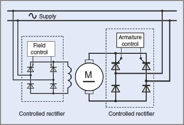
Figure 6 Solid-state control of a DC motor (circuit diagram)
Starting resistors are not usually needed because the DC voltage applied to the armature is adjusted according to the torque requirements and speed of the motor. Full voltage is not applied until the motor is up to its operating speed.
Solid-state systems for DC motors are considerably more efficient than the older motor-generator systems, while retaining their flexibility.
Reliability might be slightly less in the sense that electronic components can fail without warning. This disadvantage is decreasing as more and more progress is made with electronic component reliability.
Solid-state drives can be installed in any situation where an alternating current supply is available. In mines, where there might be explosion hazards due to the presence of gases, the solid-state motor drive is usually preferred because of inherent safety features.
The controllers eliminate the hazards of sparks that might occur with contactors and open contacts. Size is no limitation to their installation since 4000 kW fully reversing DC motor drives are already installed in mines and rolling mills.
DC Motor Starting Methods Key Takeaways
DC motor starting methods play a crucial role in ensuring smooth motor operation, preventing excessive current surges, and protecting essential components such as the armature, brushes, and commutator. By implementing proper starting techniques—whether manual or automatic—industries can enhance motor longevity, reduce maintenance costs, and improve system efficiency. Automatic starters, solid-state controllers, and acceleration control mechanisms provide precise regulation, making them ideal for applications requiring reliability and automation.