Pilot Devices Types
Pilot devices can be some type of audio-visual indicator or a type of switching device used to control the flow of energy to a process. Think about the light switch in a room. This device is used to control the flow of energy to the light and is considered a pilot device. In the off position, no light. When the light is manually switched, the light turns on. In industrial applications, these can be a push button, selector switch or contacts on a relay. Pilot Devices are used throughout the world. Their applications include residential, commercial and industrial.
What is a good definition pilot device? Pilot devices are used for man to interface with a process and a way to visually acknowledge how a process is functioning. An example of this would be using push buttons to manually start or stop a machine. When the machine starts, a light switches on to let the operator know the process has started. Pilot devices help man to interact with controlling machines and also provides a way to let machines give feedback on a process.
Pilot devices consist of push buttons, selector switches, toggle switches, indicator lights, alarm lights and any other device that interacts between man and machine.
Pushbuttons
Push buttons are a manual relay. These devices are usually limited to one or two contact blocks that are activated or switched when the button is depressed. When activated, they send a signal back to the MCP and switch on or off a load. These can be momentary contacts, that when released, returns to their normal state. Some switches use maintained contacts. When activated, the contact stays in that switched position until manually acted upon again.
An emergency stop button utilizes a maintained normally closed contact. When pressed, it opens the contacts and the flow of energy to the control circuit and the process are stopped. Push buttons are usually color coded. Red is universal for the stop. Green is usually used for start push buttons, although other colors may also be used.
Selector switch
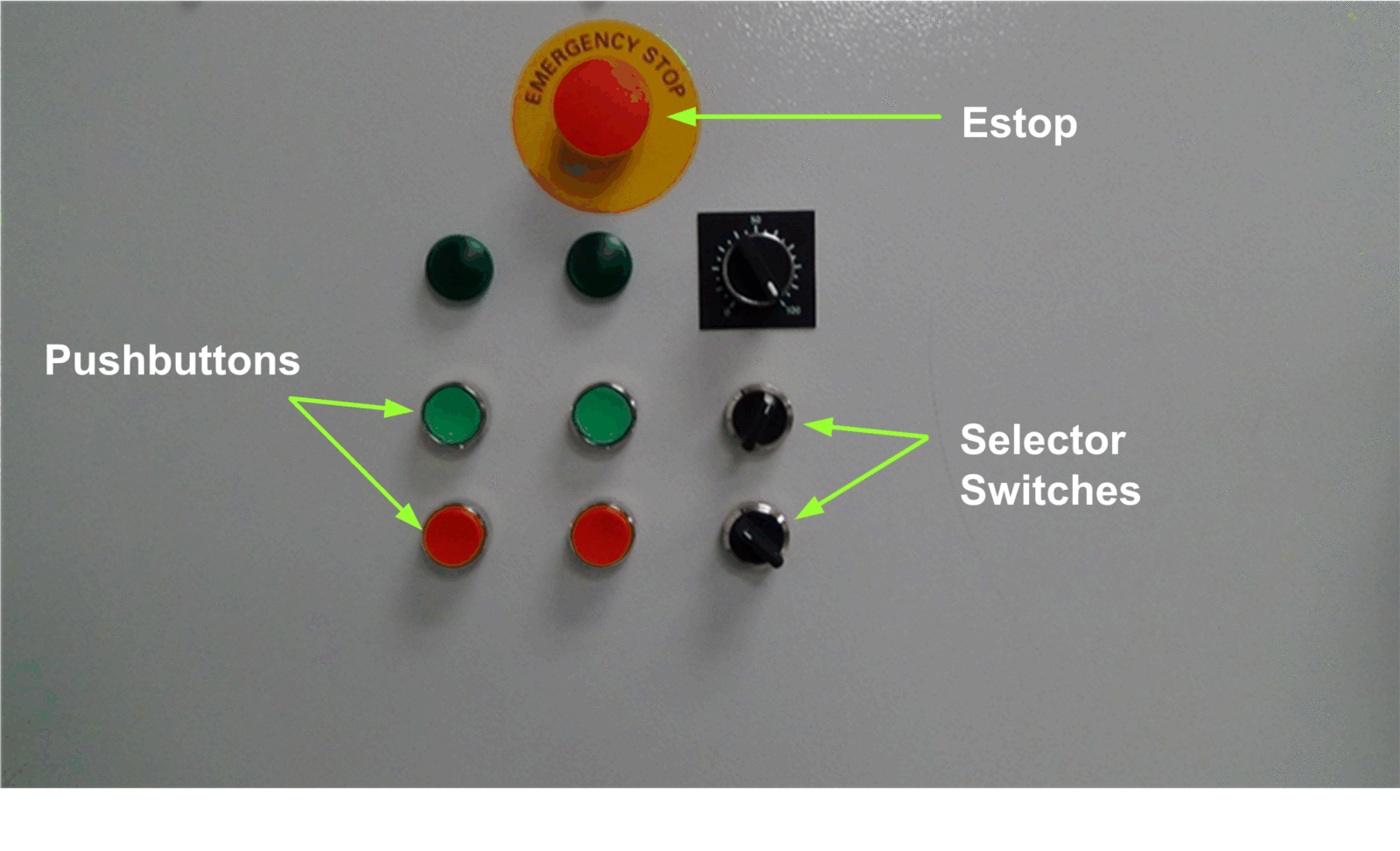
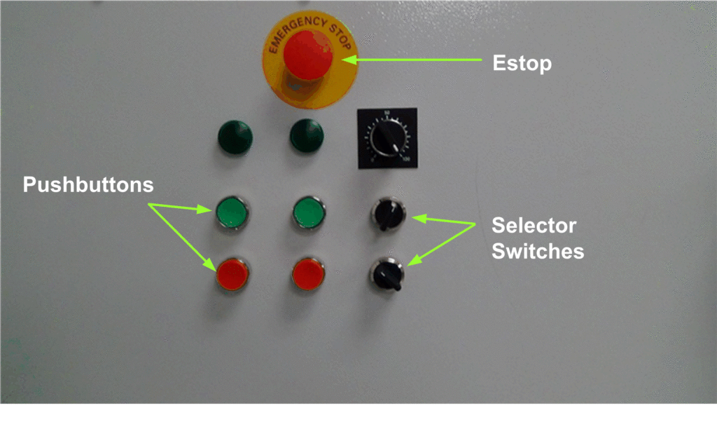
Another switching device in the pilot family is the selector switch. These switches can have two, three or more positions, depending on the application. Selector switches have a handle that can be rotated, instead of depressed. As it rotates, it pushes a plunger inward to make or break contacts mounted on the back. A selector switch can be used to switch a process from on to off, auto to manual, low speed to high speed and many other applications that call for circuit logic to be changed. Below, pushbuttons, selector switches, and E-Stop are identified.
Figure 1 – Pilot Devices
Pilot devices are not limited to just these three types of switches. There are many different types of switches: rocker switches, toggle switches, and rotary switches to name a few. All operate on the same principle; operator interface to open or close a contact to transfer information and process change.
Traffic Light
Other types of pilot devices include the audio and visual. A traffic light is a process where you know to stop at a red light, slow when the yellow light is on and proceed when a green light is on. These are all pilot devices. They do not control the car movement but give visual feedback to the operator to make a decision. Industrial pilot devices work the same way. A panel may have many indicator lights for close proximity or stack lights to monitor a process from a distance.
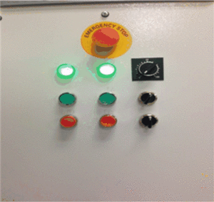
Indicator lights are usually individual lights with one color. They can be of the incandescent type (bulbs) or may be of the newer, LED type. They are usually located on the front panel of the MCP to give the operator feedback that a circuit has been energized. Below are examples of the indicator light.
Figure 2 – Indicator Lights on Front of MCP
Stack Lights
Stack lights are usually mounted in a higher position and are larger in size. They are designed this way to be viewed at a further distance. The distinguishing characteristic is that they are easily customized. Stack lights are configured to be “stacked” on top of each other, vertically or horizontally. One stack light may be used or seven; it depends on the operation. Different colors are used on each light, each one giving a different visual representation of the process.
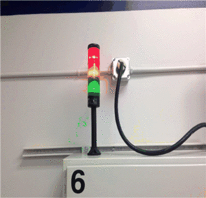
In the picture below, notice that three lights are used. The red one could mean the process is stopped. The green one could indicate that the process is running and the yellow one could indicate a fault condition that needs attention.
Figure 3 – Stack Light


