Low Voltage Components
Low voltage components make up the other half of the motor controls panel. Voltage is reduced and distributed to different components to achieve the desired function. This is a twofold purpose: safety and power consumption. By reducing the voltage, technicians that troubleshoot a live panel are less likely to be injured with the lower voltage. Operating costs are reduced by consuming less power to switch devices on and off.
Transformer
The high voltage is reduced by a device called a transformer. Transformers are the most widely used machine in the world. We find them used everywhere from computers to TV’s in your personal life as well as most industrial applications. Transformers work off a principle called magnetic induction. Voltage is pushed through a larger coil of wire (primary winding) at line voltage; then transferred through magnetic induction to a smaller coil of wire (secondary). This smaller coil reduces the voltage or “steps down” the voltage to a safe useable level. The transformer circuit is then rectified or changed from alternating current (AC) to a simpler form of direct current (DC). Changing to DC voltage gives a more constant and stable voltage for control at lower levels. There is less fluctuation and the control switching is faster.
Power Supply
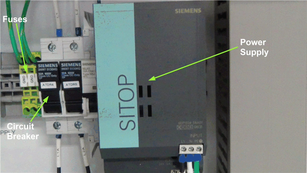
The transformer and rectifier circuit are encased together and called a DC Power Supply. High voltage AC current in; low voltage DC out. The power supply acts much like the distribution block for the high voltage side. The DC voltage is supplied to a distribution block on the low voltage side and from there it is connected to the many controlling devices on the low voltage side of the MCP. Below is an example of the power supply. Notice that it has fuse protection before the power supply to protect it from a fault. On the low voltage supply side, another type of overcurrent device is used called a circuit breaker. The circuit breaker functions just like a fuse to open the circuit in event of a fault, but has a resettable switch to close the circuit after the fault is corrected.
Figure 1- Power Supply
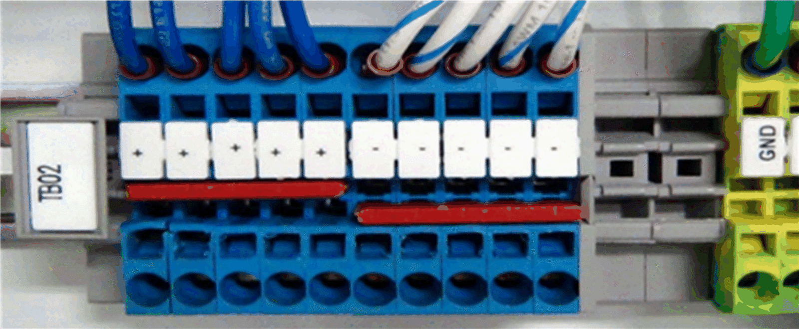
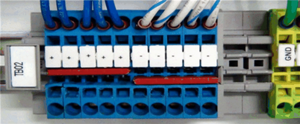
Now we know how the high voltage is reduced, we can follow it to the distribution block. All low voltage circuits will originate and terminate at the distribution block. The positive or (+) side is the starting point for the control circuit. From here it can be wired through pilot devices for switching a load on or off. From the load it is wired back to the negative terminal block (-). All circuits must have a complete path to and from the source for current to flow. The circuit should also have some type of controlling device and a load to consume the energy in a circuit.
Figure 2 – Distribution Block
Relays
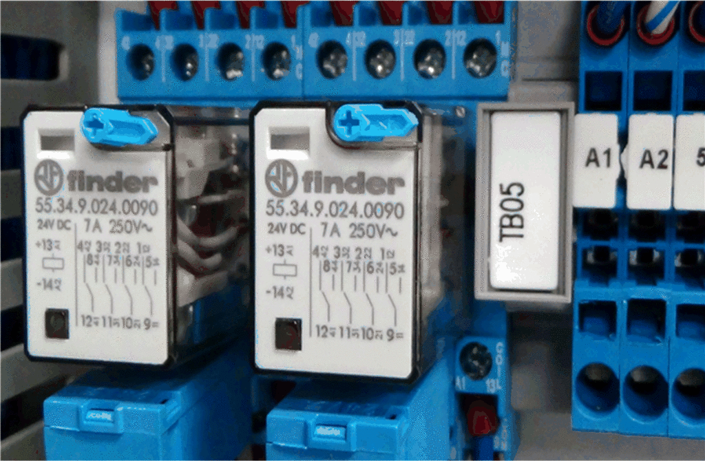
Relays are the most commonly used controlling device. A relay is an electro-mechanical device that can be used to control multiple loads with one control circuit. When a voltage is applied to the coil circuit of the relay, the coil becomes a small electromagnet. The magnet moves a plunger or lever and mechanically switches the attached contacts from their resting or de-energized state to an energized state. Relay diagrams are always shown in their de-energized state. The contacts usually have a single pole double throw configuration (SPDT). This means one set of contacts can be switched between a normally open and normally closed contact. Depending on the logic of the circuit one or both may be used. Relays can have many pairs of these contacts to switch multiple devices on or off. The picture below shows two control relays mounted in an MCP.
Figure 3 – Control Relays
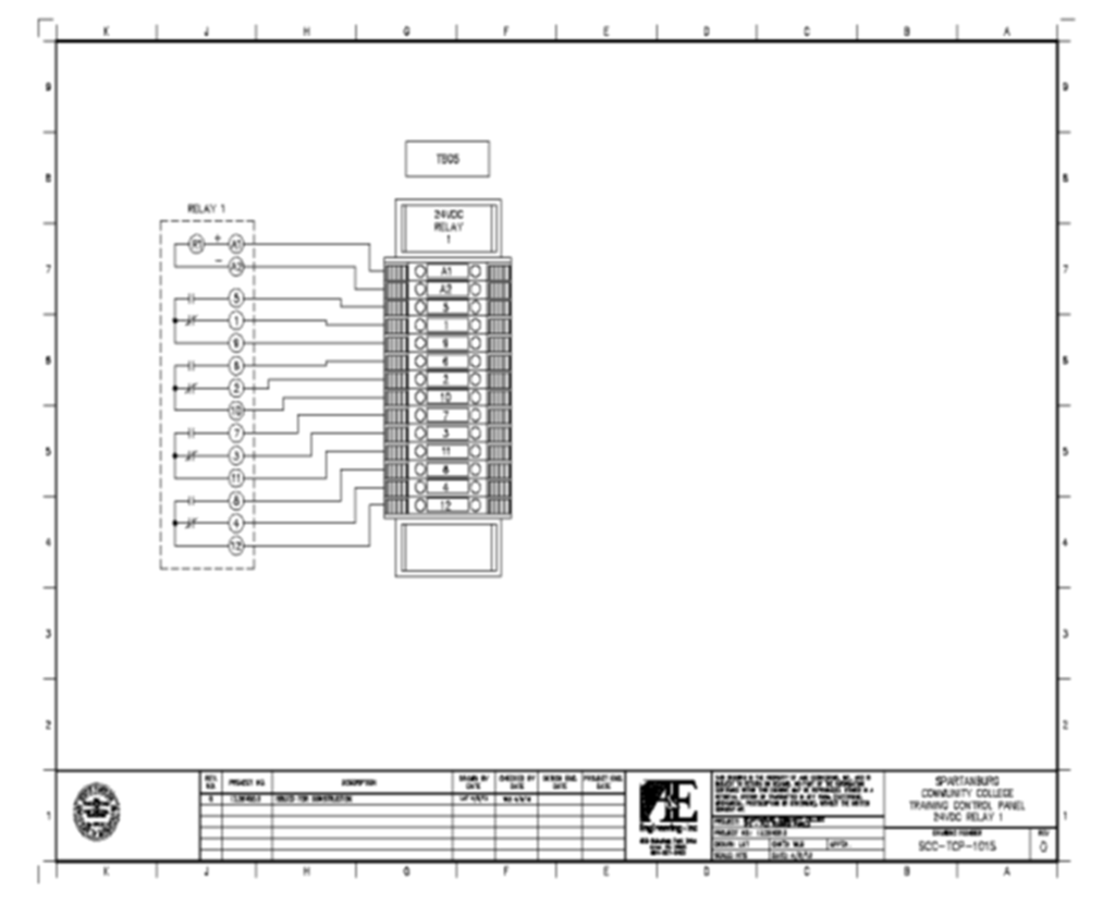
In the picture look closely at terminals (+) 13 and (-) 14. This is the universal symbol for a coil. 24vdc is applied here to switch the relay to the on position. There are 4 sets of normally open and normally closed contacts. As you can see from the diagram, terminal 12 is connected to terminal 4 with the power off. When the power is applied, this contact breaks and terminal 12 will be connected to terminal 8. Each set of contacts will work the same in the energized and de-energized state. The contacts are rating and should not be exceeded. Here we can see the contacts are rated for a current of 7 amps at 250 volts. With a small amount of voltage in the control circuit, we can control multiple devices with a much higher power rating. This is the main advantage of using relays. Below is an electrical schematic of the relay. The dashed line around Relay 1 is the same relay as the picture above.
Figure 4 – Relay Schematic
Timers
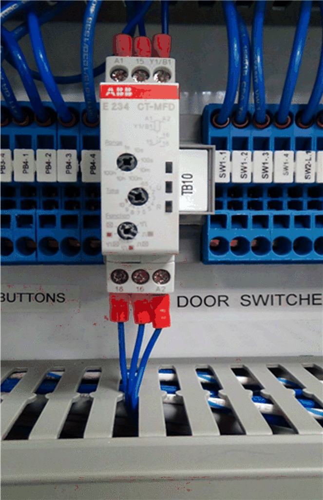
Timers work much like relays. A coil voltage is applied and loads can be switched through the contacts. The main difference is the timer will delay the switching of the contacts by a predetermined time. A time-on-delay (TON) and time-off-delay (TOF) are the two most common timers. A TON, when energized, will keep the timed contacts in their de-energized state for a set amount of time, then switch. The TOF will hold the timed contact in their energized state for a predetermined time after the voltage has been removed from the coil circuit. An example would be two motors, one starts 10 seconds after the first one switches on. A TON would be used to control the motor delay start. Newer timers have adjustable settings, saving time and money by purchasing one-timer that can perform both functions. The timer below has adjustable settings.
Figure 5 – Timer Relay
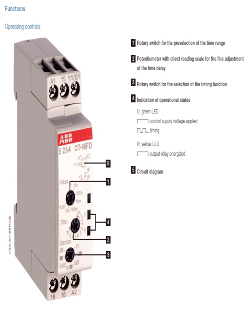
The timer above has adjustable time ranges, adjustable time settings, and multiple functions. It can be programmed to be used as a TON, TOF, one shot and pulse timers. A one-shot timer briefly turns the coil voltage on then off, but the timing function is set active. A pulse timer works off a set number of coil pulses to perform the timing function. Below is the datasheet of this timer.
Figure 6 – Timer Data Sheet (image courtesy of ABB Controls)
Programmable Logic Controller (PLC)
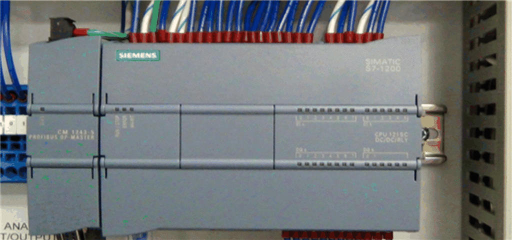
The last controlling component on the low voltage side of an MCP is an optional device and not found on all MCP’s. It is a Programmable Logic Controller (PLC). PLC’s have the capability to automate the entire MCP through software programming. PLC’s utilize all the components we have covered as controlling devices and some not covered. PLC’s have internal relays, timers, and counters. PLC’s incorporate programming software to apply logic for controlling a process. PLC’s receive inputs and control outputs based on the software logic. PLC’s provide a low-cost way to automate a process. Troubleshooting and diagnostics are built into the software to help technicians narrow down problems. Once the software logic is programmed, it can be duplicated and loaded in as many MCP’s as needed to control a process.
Figure 7 – PLC
