Motor Panel Overview
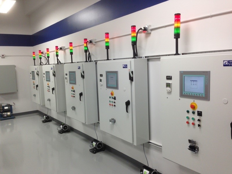
Motor Control Panels (MCP) are used in just about every type of industry; from offshore drilling platforms to a production line that makes pastries and cookies in a bakery factory. It empowers the manufacturer to be able to duplicate and automate their process with little or no human intervention. It would be almost impossible today to enter a manufacturing facility and not encounter some type of automation controlled by a motor control panel.
Imagine an automobile manufacturer with cars moving down an assembly line. The line is driven by various motors, which are controlled from a motor control panel. This motor and assembly line may be stopped at each station for fitment and started again to reach the next assembly station. The line may need to be stopped and started many times before reaching its final destination. This task can be accomplished, with or without human intervention, by a motor control panel.
Motor Control Panel Purpose
Motor control panels are designed by control engineers and pre-wired by technicians with a certain logic in mind. This logic is designed to accomplish or semi-automate a process. The contents of a motor control panel are universal. It is the way these components are connected or wired together that makes them specific to a process. Components include electro-mechanical devices such as switches, contacts, relays, motor starters and overload protection devices. We will look at these individually later in the resource.
Motor control panels also have another purpose. They give us a way to turn on or off high power circuits by using a low voltage control circuit. This provides a safety feature for technicians and also saves the user in power consumption costs. It would be very dangerous to have a system wired with high voltage controls that operators use to start and stop a line or process. Most motor control panels are divided into a high voltage side, or “Line Voltage,” for motor operation and a low voltage side for control of these high power circuits. Industry commonly uses 480 volts for power circuits. A transformer is used to reduce the voltage and feed a lower voltage, such as 24 volts, to the control side.
Most motor control panels are divided into a high voltage side, or “Line Voltage,” for motor operation and a low voltage side for control of these high power circuits. Industry commonly uses 480 volts for power circuits. A transformer is used to reduce the voltage and feed a lower voltage, such as 24 volts, to the control side.
MCP Components-high Voltage Components
A motor control panel is a way of incorporating automated control into a production line by originating all power circuits and control circuits from one place. Motor control panels also provide a safety feature by providing low voltage to control applications.
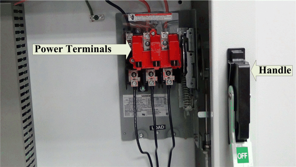
All power supplied to an MCP is routed through some type of disconnect device. (See below)
Figure 1 – Disconnect device for an MCP
Disconnect Device in MCP
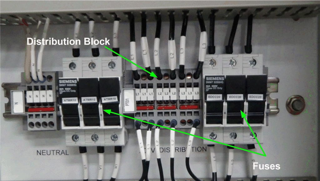
The power is wired to the top of the disconnect switch and terminated at the top three lugs (1). The handle (2) mechanically connects the top terminals to the bottom terminals. It is operated manually by a technician to provide power to the rest of the components, or by a technician in case, work is needed inside the panel. When the handle is raised to the up position, the switch is said to be “closed” and power is supplied to individual components and the panel is considered to be “live” or “hot”. Once the handle is closed, power flows to the fuse terminals for protection of branch circuits and to components through the distribution block to the low voltage control side. Here, fuses are sized for the maximum safe current draw during normal operation.
Figure 2 – Fuses and Distribution Block
Fuses and Distribution Block in MCP
Fuses are considered a safety device. They are considered to be a closed switch as long as the current draw through the fuse does not exceed its rating. If the current draw does exceed the rating, the fuse opens the circuit to protect both equipment and operator. It will have to be manually replaced by a qualified technician. A fuse of greater value cannot be used to replace that of a lesser one. If this did happen, it would let greater current flow through the devices that was designed. It could cause damage to the equipment, panel components and endanger personnel. Fuses can only be replaced with the same size or smaller current rating to ensure proper protection.
Next, high voltage power is supplied by the distribution terminals to the variable frequency drive and the motor starter. These devices operate at full line voltage because of the power requirements associated with the loads attached to them.
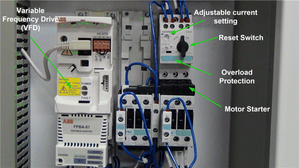
Figure 3 – Variable Frequency Drive
Variable Frequency Drive (VFD)
A variable frequency drive (VFD) is a device used to control the speed of the motor. It is unique because it can be used to start and stop a motor, as well as, vary the speed. This is critical to some processes, but in others, it may not be needed, so it is considered optional equipment. VFD’s are covered in depth later. For our purposes, it is only relevant that it is considered a high voltage component designed to control motor speed.
Motor Starter
A motor starter incorporates two basic components; a contactor for high voltage flow and an overcurrent protection device in case of a fault. Motor Starters supply full line voltage to a motor. A lower voltage is used to switch the starter on or off from the low voltage side. This is called the “coil voltage” and is greatly reduced to a safe working value like 110 or 24 volts. When the coil voltage is switched on, the line voltage is supplied to the motor through contacts in the starter. Some motor starters may have a second contactor mechanically or electrically interlocked with the one beside it. The interlock keeps both contactors from being energized at the same time. This gives us the capability to make the motor shaft turn in the opposite direction when needed. This is called a “forward-reverse motor starter.”
A motor starter always has some type of overcurrent protection built into the device. This is to protect the panel components and process in the event that something causes the motor to draw more current than it was designed. The overload protection used in the above picture has an adjustable current setting to accommodate many types of motors and it also utilizes a reset switch. If a fault occurs, the switch will automatically shut the circuit off. When the fault has been corrected, the reset switch can be reset manually to return the motor starter to normal operation.
- For More Information on Electrical Concepts: Electrical School
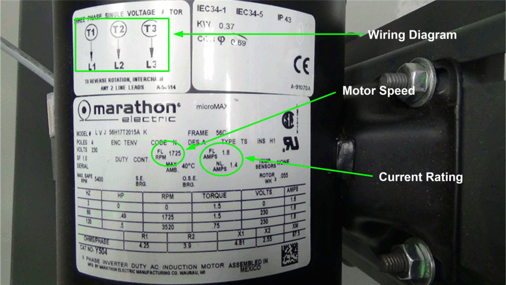
Motor starters are used for a fixed speed motor. The motor must be physically wired to the bottom of the motor starter. The motor data plate (below) should give a technician the correct wiring diagram, current draw, voltage, and speed. A motor starter has to be sized (voltage-speed-amperage) according to load or motor it is supplying.
Figure 4 – Motor Data Plate Information
