The article discusses various starting methods for three-phase induction motor, focusing on reducing high starting currents while providing adequate torque for the load. It covers methods such as Direct-On-Line (DOL) starting, Star-Delta starting, Primary Resistance (metallic and liquid resistor starters), Auto Transformer starting, Soft Start, and Secondary Resistance starting, highlighting their applications, advantages, and limitations.
A principal aim of a starter on a three phase induction motor is to reduce the starting current as much as possible while at the same time providing adequate torque to meet the requirements of the load. This article covers several starting methods of three phase induction motor along with their applications:
When a three-phase squirrel cage induction motor is connected directly to the supply, it will draw a large starting current. This current, which usually lasts only a second or two, can be up to seven times the motor’s full-load current.
Figure 1 shows the characteristics of the current and torque for a standard squirrel cage induction motor. It can be seen that the current is almost proportional to the rotor slip; as the motor builds up to speed, the slip decreases and the current decreases.
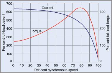
Figure 1 Speed vs. current and torque for a standard squirrel cage induction motor
A principal aim of a starter on an induction motor is to reduce the starting current as much as possible while at the same time providing adequate torque to meet the requirements of the load.
This will be a compromise because in order to reduce the starting current it is necessary to reduce the voltage supplied to the motor. However, a reduction in voltage will also result in a reduction in torque, as the motor torque is proportional to the fraction of the voltage squared. That is:
$$T\alpha V^{2}$$
This means that with 100% of the rated voltage 100% of the rated torque will be available, however if 90% of the rated voltage is applied to the motor, the torque will be reduced to (90%) 2 = 81% of the available torque. If the induction motor is being started in a no-load condition, this will be adequate but if the motor is loaded, there may not be enough torque to overcome the load and the motor will stall.
Direct-On-Line Starting Method
Direct-on-line (DOL) starting is the simplest way to start a three phase induction motor. Full voltage is applied direct to the stator windings of the stationary motor. The effect is often severe. At the instant of connection to the supply, the stator is completely demagnetized and, as the winding resistance is low, there is a high inrush of current from the mains.
At switch-on, the rotor bars behave like the short-circuited secondary winding of a transformer and aggravate the effect. It is quite usual for the starting current to reach a value seven times that of normal full-load current.
The starting torque produced is two to three times that of the full-load torque. This value of torque is transmitted to shafts, bearings, belts and the driven machine so quickly that a considerable mechanical shock is transmitted to all connected parts. If the induction motor is capable of starting the connected load, acceleration is swift. For very large induction motors (which implies a heavy load), the mechanical shock from DOL starting can shear shafts or cause severe belt slip, which results in accelerated wear.
Applications
Direct-on-line starting is generally restricted to comparatively small-size motors. Induction Motors up to 4 kW are normally started DOL but in special circumstances motors up to 25 kW have been started this way.
DOL starting is usually restricted to situations where there is little or no load imposed on the motor when being started. DOL starting a centrifugal pump is one instance where the major part of the load appears after the motor has been started when the load is gradually imposed by an increase in pressure on the liquid being forced through the pump.
Star-Delta Starting Method
For star–delta starting, the six ends of the three windings have to be brought out to the motor terminals. A reduced voltage to the windings is achieved by first connecting the windings in the star configuration, then switching to delta to apply rated voltage when the motor is up to speed.
For a 400 V winding, the applied voltage for each phase is reduced to 230 V or 58 per cent of the rated voltage. Effectively this reduces the starting torque to 33 per cent (T ∞ V2) of that obtained with DOL starting.
$$\textrm{Note that } 58^{2}=33\textrm{%}$$
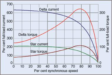
Figure 2 Comparison of current and torque characteristics for star and delta connections
If the star connection has sufficient torque to run the induction motor up to about 75 per cent or 80 per cent of full-load speed, then the motor can be reconnected in delta configuration to enable it to accelerate to full speed for normal operation. It also means that there has to be a short time lag between the starting and running periods while the motor windings are isolated from the power supply and reconnected in delta configuration.
In the star connection, the line and phase currents are equal but when the windings are reconnected in delta configuration, this condition no longer applies. The phase voltage increases by a ratio of √3 or an increase of 173 per cent. Consequently, the phase currents increase by the same ratio. The line current increases to three times its value in the star connection. These values are illustrated in Figure 3 for a winding impedance of 24 Ω.
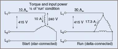
Figure 3 Comparison of star and delta starting in three phase induction motor
During the transition period the inertia of the motor and connected machine must allow free running with little deceleration. It also means that while ‘coasting’ it might generate a voltage of its own and on reconnection to the supply, this voltage can randomly add to, or subtract from, the applied line voltage.
In most cases, it causes a transient current that can be up to twenty times that of normal running current. While it only lasts for a few milliseconds, it still causes voltage surges or spikes on the supply lines. These are referred to as changeover transients.
In an endeavor to eliminate any changeover transients caused during the open-circuit interval, a closed-circuit transition star–delta circuit was developed. It has resistors in parallel with each phase winding. The resistors must be substantial enough to withstand starting currents.
In this method, when the star point of the windings is opened for reconnection to delta, the resistor star point remains closed, and current flows through the resistors and windings in series. This reduces the tendency for the motor to slow down and eliminates many of the transients. After connection to delta, the resistors are short-circuited to eliminate any current flow through them.
This starter is much more expensive than a conventional star–delta starter. It needs at least one extra contactor as well as the extra resistors. Because of the expense and its relatively few advantages, the starter is seldom used. It is only mentioned here to illustrate the point that transients can be troublesome in an installation.
Applications
Star–delta starting is a relatively simple way to get a three phase induction motor up to speed without causing excessive starting currents. It can be used in any application where the motor can be started ‘unloaded’.
Other applications include driving centrifugal pumps where little starting torque is required until the pump is up to speed and working. Other uses are on farm dam pumps, and at the end of long runs where DOL starting would cause an appreciable voltage drop.
Another use is in lathes where a clutch is incorporated in the mechanism. The three phase induction motor is started and later the clutch is engaged to turn the lathe. Many large fans or blowers can be started with a star–delta starter.
Primary Resistance
For primary resistance starting, resistors are connected in series between the supply lines and the motor terminals, although inductors are occasionally used in place of resistors. The intention is to reduce the actual voltage at the motor terminals and so limit starting current. Starting torque is reduced at the same time.
Metallic Resistor Starters
The traditional method of primary resistance starting is to insert metal resistors in series with the supply for starting (see Figure 4).
Once the induction motor has accelerated to about 75 to 80 per cent of its rated speed, full voltage is then applied to the motor. This is usually done by short-circuiting the resistors in each phase. While this type of starter is more expensive than a DOL-type starter, the method does have advantages.
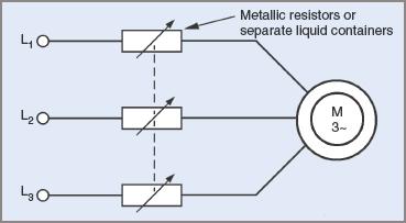
Figure 4 Basic power circuit for primary resistance induction motor starting
As the motor accelerates its starting current decreases. This in turn causes a decreased voltage drop across the resistors and an increased voltage at the motor terminals.
The overall effect is to give an increased torque as the motor accelerates. Opposing this is the effect of the resistors getting hot during the starting process and increasing their resistance slightly.
Because the motor is not disconnected from the supply when the resistors are shorted out at the changeover from the start to run connections, there is no transient current.
Liquid Resistor Starters
A similar technique uses liquids in lieu of metallic resistors. Liquid containers are far bulkier and less robust than metallic resistors, but modern liquid electrolytes have the ability to reduce their resistance as they are heated up by starting currents flowing in the liquid.
Compared with older types where metal electrodes were manually wound down into a liquid to accelerate the induction motor, the present-day types of starter use a liquid that can be adjusted in content to suit particular applications.
Often non-corrosive, it is placed in sealed and insulated containers to reduce contact with the atmosphere. Occasionally a non-reactive oil may be placed on the surface to further isolate the electrolyte from the atmosphere and prevent evaporation.
The electrodes are permanently immersed in the liquid (see Figure 5). Once in position they need no further adjustment. Depending on the manufacturer, the plates may be flat and parallel or consist of a series of short concentric cylinders placed one inside another. Each phase winding has its own separate container and set of electrodes.
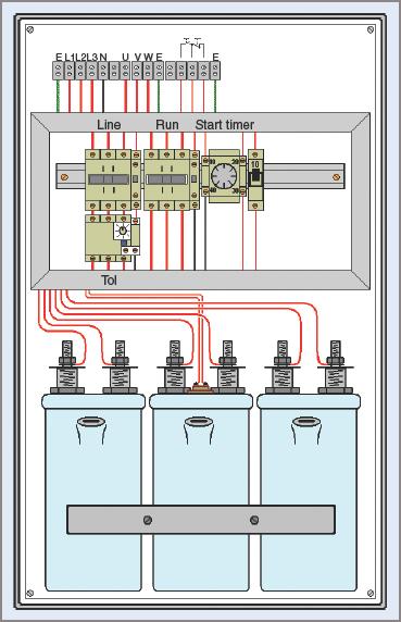
Figure 5 Typical liquid resistance starter for three phase induction motor
When the three phase induction motor is first started, the liquid has a resistance modified to suit the application. Starting current and torque is limited to predetermined values. The voltage appearing at the motor windings is reduced and the starting torque is also reduced. When properly adjusted, the induction motor is able to start and accelerate smoothly without mechanical shocks.
As the starting current flows, it heats the liquid and its internal resistance is reduced. Consequently, the voltage to the motor increases and this action is a progressive one up to about 80 to 90 per cent of full-load speed when the resistance of the liquid stabilizes. Then a timer operates a contactor, which bridges out the electrodes in the liquid and the motor can accelerate to full speed.
The primary resistance starter takes more power from the line than some starters but does so at a higher power factor. The liquid starter possibly increases the acceleration rate of the induction motor so that it reaches full-load speed more quickly.
Like the metallic resistor starter, there is no open-circuit transition stage, so it eliminates transients in both starting current and torque. The first method uses a metallic positive temperature coefficient resistor while the second method uses a liquid negative temperature coefficient element. It is this fact that enables the liquid-type primary resistance starter to have an advantage over the metallic resistor type.
Applications
Because of the lowered starting torque, the primary resistance method of starting three phase induction motors is limited to loads where initial starting torque requirements are comparatively low, that is, loads where the running torque only comes into play at full speed. Such uses as fans, blowers and water pumps are the usual applications.
Three Phase Induction Motor Starting Example 1
A 415 V, three-phase induction motor draws 160 A when connected DOL. If a primary resistance starter is connected to the motor so that the voltage to the motor is reduced to 291 V for starting, determine the:
(a) Percent of rated voltage applied to the motor during starting
(b) Starting current taken by the motor
(c) Percentage of DOL starting torque produced.
(a) Percent rated voltage:
$$\textrm{Percent Voltage}=\frac{291\times 100}{415}=\textrm{70%}$$
(b) Starting current:
$$I_{s}=\textrm{70% of DOL starting current}=\textrm{70% of 160A}=0.7\times 160=112A$$
(c) Percent starting torque:
$$T_{s}\textrm{%}=\left ( 70\textrm{%} \right )^{2}\textrm{of DOL torque}=\textrm{49% DOL torque}$$
Autotransformer Starting Method
Autotransformer starters generally use two autotransformers connected in an open-delta configuration to provide reduced-voltage starting. Taps are usually provided on the transformers to enable selection of the required starting torque. The principle is illustrated in Figure 6.
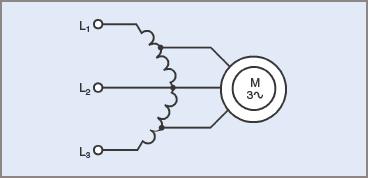
Figure 6 Starting connections for three phase induction motor using an open delta transformer
Points to note are:
1. The motor starting current varies directly with the applied motor voltage.
2. The line current varies as the square of the motor voltage.
3. The torque varies as the square of the motor voltage.
Point 2 means that the starting current with an autotransformer starter is less than that obtained with a primary resistance starter. This is its major advantage: for the same starting current the motor torque is increased.
Point 3 means that if a 50 per cent voltage tapping is chosen, then the resultant starting torque is 25 per cent of full-load torque. A tapping has to be selected that will be the minimum that enables the induction motor to start against its load.
The major characteristics of this type of starter are:
1. Low line current
2. Low line power
3. Low power factor
4. Open-circuit transition periods
5. Acceleration is in a series of steps; it is not continuous or smooth.
The provision of tappings on the transformers makes it possible for a choice of voltages (and hence currents) to be available for starting purposes.
The use of a transformer makes it possible to reduce the line input current at a greater rate than that at which the torque is reduced. With a transformer:
$$\textrm{Input Voltage}\times \textrm{Input Current}=\textrm{Output Voltage}\times \textrm{Output Current}$$
$$V_{1}\times I_{1} =V_{2}\times I_{2}$$
During starting, a reduced voltage V2 is applied to the induction motor, thereby reducing the starting current I2. Because of transformer action, however, the input current is reduced still further. It can be illustrated by the following example.
Autotransformer Starting Example 2
A 415 V, three-phase induction motor draws 160 A when connected DOL. If an autotransformer starter, with the motor connected to the 70 per cent tapping, is used to start the motor, determine the:
(a) Voltage applied to the motor during starting
(b) Starting current taken by the motor
(c) Starting current drawn from the supply.
(a) For 70 per cent tapping:
$$\textrm{motor voltage}= \textrm{70% of input voltage}=\textrm{70% of 415V}=0.7\times 415=290.5V$$
(b) For 70 per cent tapping:
$$\textrm{motor current}= \textrm{70% of DOL starting current}=\textrm{70% of 160A}=0.7\times 160=112A$$
(c) For a transformer
$$V_{1}I_{1}=V_{2}I_{2}$$
$$I_{1}=\frac{V_{2}I_{2}}{V_{1}}=\frac{290.5\times 112}{415}=78.4A$$
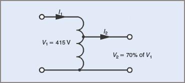
Figure 7 Circuit diagram for Example 2
Note that the induction motor voltage has been reduced by 70 per cent to 290 V. Because I ∞ V2, the torque will have been reduced to (70%)2 = 49% of the DOL value. While the motor current has been reduced to 70 per cent of the DOL value, the line input current has been reduced to 49 per cent of the DOL value by transformer action.
For a primary resistance starter to give the same reduction in line input current, the voltage applied to the motor would need to be reduced to 49 per cent of the DOL value further reducing the starting torque.
For comparison purposes see Table 1.
Table 1 Comparisons between Primary Resistance And Autotransformer Starting
| Starter type | Voltage applied to motor | Starting current | Starting torque |
| Primary resistance | 49% | 49% | (49%)2 = 24% |
| Autotransformer | 70% | 49% | (70%)2 = 49% |
A more expensive form of autotransformer starter designed to alleviate the problem of open-circuit transients is the Korndorfer starter. It uses three autotransformers and an extra contactor. Its use is limited to applications where there is no reasonable alternative. It maintains a continuous torque during the transition periods of reconnection (see Figure 8).
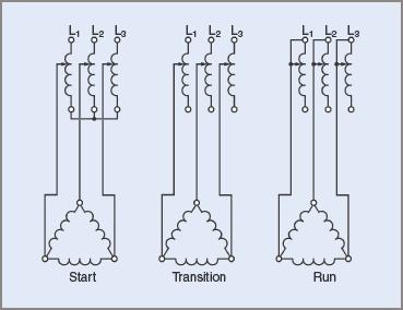
Figure 8 Autotransformer Korndorfer switching
From the diagram in Figure 8 it can be seen that during the transition period, the induction motor is connected to the supply by part of the transformer windings, which act as series inductors during the transition time.
Applications
Owing to the high cost of autotransformer starters, their use is restricted to heavy loads that have to be started from rest. Such applications are larger-type refrigeration units and air-compressors where the motor might have to start against a substantial head pressure. In some cases, electrically operated relief valves might also have to be fitted to release the head pressure to enable the induction motors to start.
Soft Starter
Three-phase induction motors are designed to operate at standard line voltages and frequencies. In Australia, induction motors are intended to run on a three-phase line-to-line voltage of (usually) 400 V and a frequency of 50 Hz. This results in the flux density in the air gap of the motor being within defined limits.
Any motor starter designed to reduce the line voltage to a motor also has a tendency to reduce the current flowing to the motor, thereby reducing starting torque.
The autotransformer method of starting goes part way to solving the problem of maintaining starting torque and current at a reduced voltage, but the method also has disadvantages.
It was reasoned that if the induction motor starting current could be manipulated to satisfy the above requirements, then the voltage and frequency might also be controlled. This line of reasoning gave rise to the electronically controlled starter. It was developed to include such refinements as control over the following:
1. Starting Currents
2. Overload Currents
3. Over- and Under-Voltage Monitoring
4. Motor Protection
5. Frequency
6. Motor Isolation
7. Sequencing Other Motors
8. Dynamic Braking
9. Low-Speed Operation
10. Slip Compensation (Better Speed Regulation)
11. Remote Computer Control.
In an electronically controlled starter (see Figure 9 overleaf), the controlling circuits are more involved than in a normal relay-operated starter. The general principle is to convert the alternating current supply to direct current, which is then fed through a filter to remove most of the transients. The DC is then supplied to an inverter to convert DC back to AC using a high-speed switching sequence. This is shown in block diagram form in Figure 10.
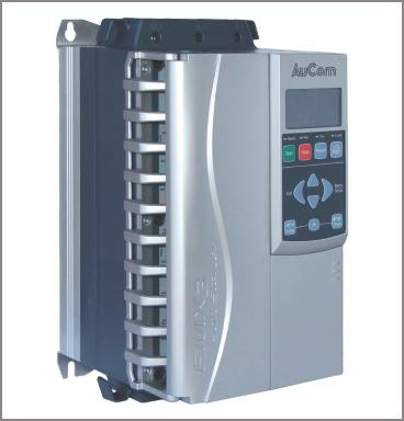
Figure 9 Electronic soft starter for three phase induction motor
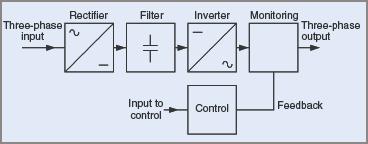
Figure 10 Block diagram for electronic motor control
The units can be programmed to monitor and control motor currents during starting and stopping sequences. This gave rise to the term ramping. It is simply a term for the control of motor current during the starting and stopping sequences.
If a graph is drawn for motor current against time, the characteristic is a straight line. In those terms, the induction motor can be ramped up or down as shown in Figure 11. These linear characteristics are highly variable and depend on the information programmed into the unit.
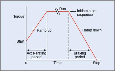
Figure 11 Ramping control in three phase induction motor
The motor current is controlled to remain within two values by the starter programming:
1. to ensure that the current never exceeds a predetermined maximum value
2. to provide a sufficient minimum value of current to ensure that the motor has sufficient torque to enable starting.
During the starting sequence, as the motor accelerates up to speed and the motor current tends to decrease, the starter increases the available current and hence the available torque is kept constant to keep the motor accelerating up to a speed governed by the frequency of the supply.
During the stopping sequence the induction motor is disconnected from the supply and brought to a rapid and controlled stop by the starter; that is, it is ramped down. On a production line, time spent waiting for a machine to coast down to a stop is time wasted, and is usually not tolerated.
In a starter of this type, there is considerable interaction between the applied voltage, the motor current and the starter-generated frequency. Electronically all three are monitored within the starter, and the result is a voltage and a frequency supplied to the motor that meet the prevailing motor conditions.
For example, an increased voltage will increase the starting current (say 10%), while an increased frequency will decrease starting current (approx. 5%). These are two opposing effects. Similarly, increasing the applied voltage will increase the starting torque, but an increase in frequency will decrease the starting torque.
The inverter and the DC being supplied to the inverter have to be continually monitored. The inverter also has the task of converting DC to AC. It does this by breaking the DC up into small units of either polarity. The resulting alternating voltage wave is only vaguely similar to a sine wave and as a result generates harmonics at a ratio many times higher than the fundamental frequency. The current waveform is filtered to some extent by the inductance of the motor windings and is closer to a sinusoidal shape.
Applications
This method can be a more expensive way for starting squirrel cage induction motors, although initial costs are being reduced constantly and for smaller motor starters the initial cost is now approaching a comparable value.
Care should be taken in selecting induction motors to be used in conjunction with these types of starters. The starters are capable of running three phase squirrel cage induction motors at speeds well above and below their designed levels.
In circumstances where there is a need to start them regularly or run them at slow speeds for extended periods, consideration must be given to cooling requirements.
The units can be made at ratings in excess of 300 kW. Since costs for the units are high, careful consideration must be given to their possible use. Centrifugal fans are one possible use and their use is more than justified in printing workshops where a printing press must be run up to speed slowly and smoothly because of the rolls of paper being fed through.
Another typical use is on production lines where several induction motors must be controlled and their speeds integrated to ensure smooth and coordinated processing.
Secondary Resistance Starting Method
Despite the predominant use of three phase squirrel cage induction motors and their improved starting methods, there are still applications where the wound-rotor motor has advantages that more than compensate for their initial cost. Apart from the high starting torque characteristics, there are still current surge limitations that cannot be met by a squirrel cage induction motor combined with any of the above starters.
The speed–torque characteristic of any three phase induction motor depends largely on the relative proportions of resistance and reactance in the rotor circuit. When the rotor resistance is equal to the rotor inductive reactance, maximum torque is produced.
At the instant of starting, while the rotor is still stationary, the frequency of the currents in the rotor will equal the line frequency. This causes increased inductive reactance in the rotor circuit. With the introduction of external resistance into the wound-rotor circuit, the rotor resistance and impedance values can be adjusted to produce maximum torque at starting and at the same time minimize starting currents (see Figure 12).
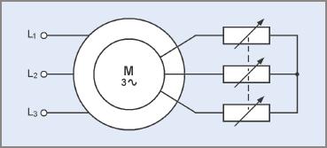
Figure 12 Basic power circuit for secondary resistance induction motor starting
Three Phase Induction Motor Starting Methods Key Takeaways
The various starting methods for three-phase induction motor, such as Direct-On-Line (DOL), Star-Delta, Primary Resistance, Auto Transformer, Soft Start, and Secondary Resistance, are crucial for balancing the reduction of high starting currents with the provision of adequate torque to meet load requirements. These methods are essential in diverse applications, from small motors in centrifugal pumps to large industrial systems like refrigeration units and air compressors. By minimizing mechanical stress, electrical surges, and energy consumption during startup, these techniques ensure efficient and reliable motor operation across a wide range of industries, including manufacturing, agriculture, and HVAC systems. Selecting the appropriate starting method is vital for optimizing performance, extending equipment lifespan, and reducing operational costs.