In this article, you’ll learn about the working principle of Moving Coil and Moving Iron meters:
To measure a voltage with greater accuracy than can be achieved with the voltage testers, a voltmeter is used. The face of the meter is calibrated in volts and the value read off against a scale.
Meters are made with varying degrees of accuracy. The greater the accuracy, the higher the cost and the more care must be taken to protect the meter. For most purposes, meters can be classified by one of two operating principles. The two major movements used are:
1. Moving-coil meters
2. Moving-iron meters.
Moving Coil Meter Working Principle
Figure 1 is an exploded view of a moving-coil movement. It can be seen that a coil free to rotate is suspended in the field of a permanent magnet. The coil ends are connected to a suspension system so that current can be passed through the coil.
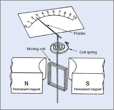
Figure 1 Exploded view of a moving-coil movement
The suspension system may consist of one of two methods:
| 1. | A coiled spring as shown in Figure 1. Sometimes called a hair spring, the outer end is attached to an adjustable arm so that the pointer of the movement can be adjusted to align itself up with the zero on the meter scale. |
| 2. | The second method is called ‘taut band suspension’ and is considered a more robust method for suspending the moving coil. With this method the rigid coil pivot is replaced with two separate thin metal strands under tension. The hair springs are no longer necessary so are usually removed. Zero adjustment of the meter is achieved by a similar movable arm attached to one of the bands. |
It must be noted that a current is passed through the coil—not a voltage. The current that flows through the coil is governed by the value of the applied voltage. The coil sets up its own field which reacts with that of the permanent magnet and causes the coil to rotate. A pointer attached to the coil gives a voltage reading against a scale.
The meter movement can only work satisfactorily on direct current. If AC is applied to the movement, it tries to turn the coil rapidly in the opposite directions with the result that the coil effectively remains stationary.
The meter can only operate on AC if the AC is rectified to DC before it flows through the meter. Because of these factors, the moving-coil meter always reads average values of current.
Moving Iron Meter Working Principle
Figure 2(a) overleaf is an exploded view of a moving-iron meter to illustrate its operating principle. In practice the construction is slightly different and is shown in Figure 2(b).
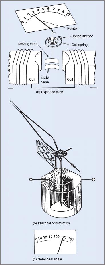
Figure 2 Moving iron meter exploded view, construction, and non-linear scale
There are two magnetically soft iron vanes in the movement. One vane is fixed and the other pivoted and free to rotate. A pointer attached to the moving vane moves across a scale as an indicator.
When an electric current is passed through the coil, both the fixed and moving vanes are magnetized and have like poles at adjacent ends. Like poles repel each other and the movable vane moves away from the fixed vane. The attached pointer then indicates a value against a calibrated scale.
A restraining spring provides opposing torque so that the vane movement can be stabilized.
Like the moving-coil instrument, the moving-iron meter is current operated. The current that flows through the coil is governed by the applied voltage.
As a voltmeter, the coil impedance is very low when compared with the required series resistance. Consequently the meter movement can be considered as resistive only and the current through the meter is directly proportional to the applied voltage (Ohm’s law).
The meter will operate on both DC and AC, although it might need to be calibrated differently. Because the two vanes are magnetized by the same current, the moving-iron meter operates on root-mean-square (RMS) values of current.
The major difference in scale calibration is that the moving-iron meter has a non-linear scale. This is illustrated in Figure 2(c).
Extending the Range Of Voltmeters
Both moving-iron and moving-coil meters are current-operated and relied on magnetic effects for their operation. However, the meter scales may be calibrated as voltage because of the direct ratio between voltage and current.
The basic movements of both types often have only a small voltage drop across the operating coils. Typically for a modern moving-coil meter this voltage is in the order of a few millivolts. While the moving-iron type has a slightly higher voltage drop it is still very low and this factor limits the uses of these meters unless steps are taken to extend their operating range.
For any given voltage, adding series resistance decreases the current flow through the meter. If a moving-coil movement with 100 Ω coil resistance has an extra 10 kΩ added in series, the total meter resistance circuit would be 10.1 kΩ. From Ohm’s law the current is now reduced approximately 10 times. To restore the operating current to its original value, 10 times the voltage must be applied; that is, the voltage range of the meter is extended 10 times.
Moving Coil Meter Example 1
A moving coil meter (Figure 3) has an internal resistance of 100 Ω. Find:
(a) the voltage drop across the meter if 1 mA gives a full-scale deflection (FSD) of the pointer.
(b) the voltage that would have to be applied to give full-scale deflection of the movement if a resistance of 10 kΩ is connected in series with the meter
(c) the new full-scale voltage if the series resistance is replaced with one of 1 MΩ.
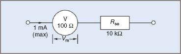
Figure 3 Circuit for Moving Coil Meter Example
(a) Voltage across meter:
$$V_{M}=IR=1\times 10^{-3}\times 100=0.1V$$
(b) Rse = 10 kΩ.
Maximum current of meter is 1 mA.
Total resistance = 10 000 + 100 = 10 100 Ω:
$$V=IR=1\times 10^{-3}\times 10100=10.1V$$
(c) Rse = 1 MΩ.
Maximum current is still 1 mA.
Total resistance = 1 000 000 + 100 = 1 000 100 Ω:
$$V=IR=1\times 10^{-3}\times 1000100=1000.1V$$
The full answers for voltage have been given in (b) and (c) but in normal practice they would be rounded off to 10 V and 1000 V.
In summary, for a moving-coil meter, a series resistor of 10 kΩ enables the meter to be used as a 10 V meter. Similarly, a series resistance of 1 MΩ enables the meter to have a full-scale rating of 1000 V.
For moving-iron meters used as voltmeters, a similar situation applies. Once the full-scale current value and the internal resistance of the movement are known, series resistors can be added to extend the maximum voltage range of the meter. These two facts are often inscribed on the face of the meter for identification purposes. These added series resistors are known as multiplying resistors or simply multipliers.
Moving Iron Meter Example 2
A moving-iron meter has the following inscribed on its face: ‘FSD 5 mA, Resis 25 Ω’. Find the full-scale voltage ranges for series resistors of 10 kΩ and 1 MΩ.
Voltage across meter at full-scale deflection:
$$V=IR=5\times 10^{-3}\times 25=0.25V$$
The 10 kΩ series resistor:
$$V=IR=5\times 10^{-3}\times \left ( 10000+25 \right )=50V$$
The 1 MΩ series resistor:
$$V=IR=5\times 10^{-3}\times \left ( 1000000+25 \right )=5000V$$
Extending the Range Of Ammeters
The operating current of an ammeter is generally very low to ensure adequate sensitivity for measuring small values of current. The internal resistance of the meter is also kept as low as possible to reduce the voltage drop across the meter itself.
To measure values of current higher than that required to give full-scale deflection, a resistor called a shunt is placed in parallel with the meter. It allows some of the current to bypass the meter. Any fixed value of current flowing into a parallel circuit will divide according to the resistance of the paths. The less the resistance the greater will be the current flow in that path. It is better explained with an example, using the same meter movement as that in Example 1.
Example 3
A moving-coil meter movement has a full-scale current rating of 1 mA and an internal resistance of 100 Ω. calculate the resistance of a shunt to be placed in parallel with it so that currents of up to 1 A can be measured. The circuit is shown in Figure 4 overleaf.
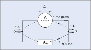
Figure 4 Circuit for Example 3
The intention is to bypass 999 mA around the meter with Rsh, so leaving only a maximum of 1 mA to flow through the meter.
Meter voltage at FSD:
$$V=IR=1\times 10^{-3}\times 100=0.1V$$
Because the shunt resistor and the meter are in parallel, the voltage across the parallel section will be the same for both resistors; that is, the voltage across the shunt = 0.1 V. This means that two of the three values required to apply Ohm’s law are known. (It has already been established that 999 mA must bypass the meter.) Thus:
$$R_{sh}=V/I=0.1/0.999=0.1\Omega$$
Example 4
A meter movement has a full-scale deflection current of 500 μA and an internal resistance of 40 Ω. calculate the value of a shunt resistance to extend the meter range to 300 mA. The circuit will be similar to that of Figure 4, although the values will be different.
Current to bypass meter:
$$300mA-50\mu A=\left ( 300\times 10^{-3} \right )-\left ( 50\times 10^{-6} \right )=0.29995A$$
Voltage across the meter at FSD:
$$V=IR=50\times 10^{-6}\times 40=0.002V$$
Resistance of shunt:
$$R=V/I=0.002/0.29995=0.0066\Omega$$
In practical terms, to extend the range of an ammeter 1000 times, a shunt resistor must be placed in parallel with the meter. Its resistance will be one-thousandth that of the meter movement.
It should be appreciated that the values indicated on the meter scale have to be corrected for the new range of the meter; that is, at an indicated half-scale reading of 0.5 mA, the actual current would be 500 mA.
For some meters, and particularly DC meters, shunts of very low values of resistance are required. Small errors in resistance can lead to much bigger errors in current readings.
Moving-iron meters on AC often use a special type of transformer called a current transformer to eliminate the possibility of shunt calibration error. In conjunction with voltage transformers used to extend the range of voltmeters.
Moving Coil and Moving Iron Meters Key Takeaways
Moving-coil and moving-iron meters play a crucial role in electrical measurements, ensuring accurate voltage and current readings across a wide range of applications. These meters are essential in industries such as electronics, power systems, and instrumentation, where precise measurements are critical for efficiency and safety. By extending the range of voltmeters and ammeters through series resistors and shunts, these instruments can be adapted to measure a vast spectrum of electrical values. Their ability to operate on both AC and DC (in the case of moving-iron meters) makes them versatile tools in electrical engineering and testing. Understanding their working principles and applications is fundamental for engineers, electricians, and technicians who rely on accurate readings to diagnose and maintain electrical systems.