The article provides an overview of single phase and three phase transformer construction, including core types, winding arrangements, and structural differences. It discusses various core configurations such as core-type, shell-type, and toroidal designs, as well as their applications, advantages, and factors influencing their selection for different voltage and current requirements.
Single-Phase Transformer Cores
A transformer consists of a common magnetic circuit linking the primary and secondary windings. The form of construction is determined by the arrangement of the laminations and the way they are stacked together. Figure 1 shows two methods for making up the stack for a transformer core.
Figure 1(a) shows U–I shaped laminations, which are stacked in alternate directions to make a core-type magnetic circuit. Figure 1(b) shows E–I shaped laminations, which are also stacked in alternate directions to make a shell-type magnetic circuit.
Either type can be stacked from simple rectangles of lamination sheet that is the preferred method for larger transformers. Although there are several variations of these types of construction, transformers may in general be classified as one of these two types—U–I or E–I.
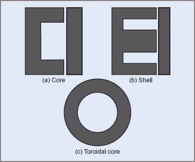
Figure 1 Core, shell and toroid types
Transformers are also separated into groups known as core, shell and toroidal.
Core Type
With the core-type transformer, the windings surround the laminated core (see Figure 2(a)). To provide a uniform flux density throughout the magnetic core, the cross-sectional area of the core is uniform.
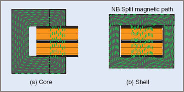
Figure 2 Windings—core and shell
Shell Type
The shell-type construction has the magnetic core surrounding the windings (see Figure 2(b)). Because the core provides a parallel magnetic path for the flux, the center limb is twice the cross-sectional area of the outer limbs, maintaining uniform flux density throughout the iron core.
By comparison, the core-type construction has a lighter core of smaller cross-sectional area, but a greater length of magnetic circuit. It also has a relatively greater number of turns, but these have shorter mean length.
The core type, with its larger window space, is more suitable for higher voltages requiring many turns and a larger space for insulation. The shell type is particularly suited for moderate voltages requiring fewer turns, less insulation, larger currents and lower frequencies, with corresponding flux densities.
Toroidal Type
The toroidal core is made from a continuous ribbon of thin metal tape made from a special alloy. It is wound tightly around a former and consolidated under pressure into a solid mass. Toroidal cores must be wound by a special machine that passes the coil wire through the center of the toroid many times.
One advantage of the toroidal type is that the windings are spaced around the whole core, resulting in a shorter, constant cross-section magnetic path, with very low leakage flux (see Figure 3).
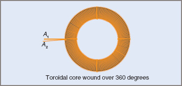
Figure 3 Toroidal winding
A toroid core may alternatively be sliced into two C-shaped pieces—the finished article is sometimes referred to as a C-core. The cut faces are ground to ensure good surface contact between the two halves. Two of these halves are placed around the transformer windings and clamped with a metallic band under moderate pressure to counter the effect of an air gap.
For core-type construction using C-cores, one pair of cores is used, while for shell-type construction, two pairs or C-cores are used. It is usual to place a third clamp around the pair of cores after assembly to prevent noise and chafing by vibration.
For three-phase transformers, three sets of C-cores are used so each coil has two C-cores through the coil set.
Single-Phase Transformer Winding Arrangements
The actual placement of the windings on the transformer core depends on the type of core and the intended use of the transformer. Other factors that influence this arrangement are the operating frequency and the size or power rating of the transformer.
Some typical winding layouts are shown in Figure 4. While the core-type transformer construction is shown in the diagrams, the winding arrangement applies equally to the shell-type construction.
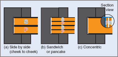
Figure 4 Single-Phase Transformer Winding arrangement
With the concentric method, one winding is wound on the top of the other (primary or secondary) and suitable insulation is installed between the two. A sandwich or pancake-type winding is used where closely coupled windings are required, so that the magnetic leakage can be reduced to a minimum.
The sandwich method is also used in large distribution transformers for ease of winding and handling, and also in smaller transformers operating at higher audio frequencies.
The type of winding arrangement that is now becoming more common for power transformers is shown in Figure 4(c). This is due in part to Australian Standards recommendations for insulation requirements between primary and secondary windings.
- You May Also Read: Difference between Core type and Shell type Transformer
Three-Phase Transformer Cores
The same variations in single-phase cores apply to three-phase cores. For single-phase, the majority of transformer cores use the shell-type construction, while for three-phase, the majority are of a core-type construction.
A three-phase transformer can be obtained by using three identical single-phase transformers, but usually a common three-phase magnetic core is used, with three identical sets of primary and secondary windings mounted on it.
Three-Phase Core Type
The shape shown in Figure 5(a) is usually employed in smaller distribution-type transformers. The core-type construction has a shorter length per turn of winding than the shell type but has a longer magnetic path. While similar in appearance to the single-phase shell type, each leg of the core has an equal cross-sectional area.
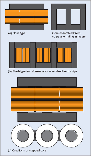
Figure 5 Three-phase Transformer core types
Three-Phase Shell Type
This shape of core overcomes the tendency of the core type to have unequal flux densities (see Figure 5(b)).
Three-Phase Cruciform or Stepped Core
With conductors of large cross-sectional area, it becomes difficult to construct windings that have 90° bends in the conductors. With this shape of core the windings are wound on circular formers and the core is stepped (in a cross-sectional area) to fill up the inside of the coil as far as possible with transformer laminations.
The core is shown in cross-section in Figure 5(c) and it can be seen that a great number of different-sized laminations are required. This form of construction is expensive and is generally used only on large transformers.
Three-Phase Toroidal
This type of construction can be obtained in most shapes for three-phase transformers (see Figure 6).
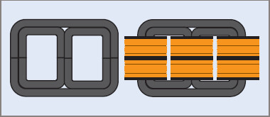
Figure 6 Three-phase C-core formed from rolled and bonded transformer steel strip
Three-Phase Transformer Winding Arrangements
The same factors affecting windings and cores for single-phase transformers apply to three-phase transformers, although the majority of distribution transformers are wound in the sandwich or pancake style. The method lends itself to ease of construction and repair.
The degree to which the primary and secondary windings are magnetically coupled depends on the intended purpose of the transformer.
A transformer is said to be close coupled when all the primary flux passes through the secondary turns. If a large proportion bypasses the secondary windings, the transformer is said to be loosely coupled.
There are of course intermediate degrees of coupling. For example, a distribution transformer is less than close-coupled as a form of current limitation, to allow for the case of damage to overhead lines connected to its secondary. However, the degree of coupling for a high-tension transformer for an illuminated sign is far less than that for a distribution transformer. In this case it is required that the on-load voltage be considerably less than the open-circuit voltage.
Single & Three Phase Transformer Construction Key Takeaways
The construction and winding arrangements of single-phase and three-phase transformers play a crucial role in determining their efficiency, reliability, and suitability for various applications. Core-type, shell-type, and toroidal transformers each have distinct advantages that make them ideal for specific voltage and current requirements. Understanding these differences is essential for selecting the right transformer for power distribution, industrial machinery, electrical appliances, and specialized applications like high-frequency circuits. The choice of transformer design directly impacts energy efficiency, electromagnetic interference, and thermal performance.