The article covers single-phase and three-phase transformer connections, their applications, and configurations, including wye and delta connections. It also explains transformer secondary taps, center-tapped transformers for residential power distribution, and control transformers used for voltage reduction in electrical systems.
Transformers may be connected in various configurations depending on the application. Configurations consist of single-phase and three-phase connections. Single-phase connections are typically found in residential applications, while three-phase connections are found in commercial and industrial applications.
High voltage transformer windings are marked H1, H2, etc., and low voltage transformer windings are marked X1, X2, etc.
Single-Phase Transformer Connections
Electricity is used in residential applications (one-family, two-family, and multifamily dwellings) to provide energy for lighting, heating, cooling, cooking, etc. The electrical service to dwellings is normally 1φ, 120/240 V.
The low voltage (120 V) is used for general-purpose receptacles and general lighting. The high voltage (240 V) is used for heating, cooling, cooking, etc.
Residential electrical service may be overhead or lateral. Overhead service is an electrical service in which service-entrance conductors are run through the air from the utility pole to the building.
Service lateral is an electrical service in which service-entrance conductors are run underground from the utility system to the service point. See Figure 1.
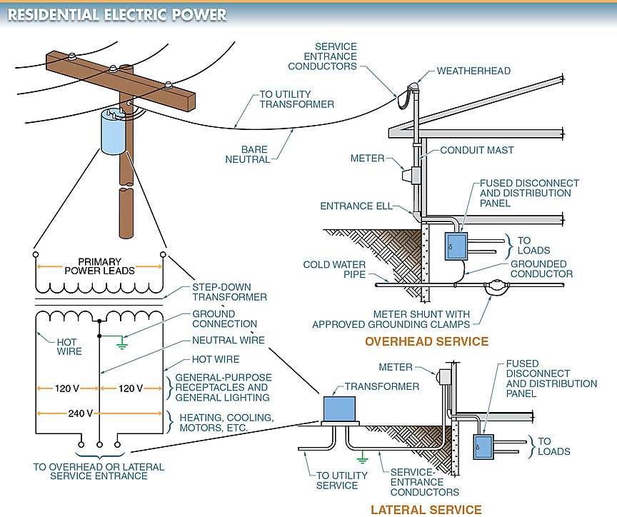
Figure 1. Overhead or service lateral may be used to supply power to a residential building.
Three-Phase Transformer Connections
Three 1φ transformers are connected to develop 3φ voltage. The three transformers may be connected in a wye or delta connection.
In a wye connection, the end of each coil is connected to the incoming power lines (primary side) or used to supply power to the load or loads (secondary side). The other ends of each coil are connected together.
In a delta connection, each transformer coil is connected end-to-end to form a closed loop. Each connecting point in a delta connection is attached to the incoming power lines or used to supply power to the load or loads.
The voltage output and type available for the load or loads is determined by whether the transformer is connected in a wye or delta connection. See Figure 2.
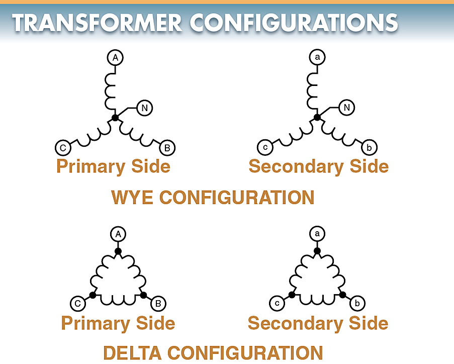
Figure 2. Three-phase transformers may be connected in a wye or delta configuration.
Transformer Secondary Taps
Many transformers have a secondary coil that has an extra lead (tap) attached to it.
A tap is a connection brought out of a winding at a point between its endpoints to allow the voltage or current ratio to be changed. Taps allow different output voltages to be obtained from a transformer. See Figure 3.
For example, the output voltage between leads 1 and 2 is 120 VAC because the turns ratio is 1:1 (100 to 100). The output between the tap and lead 1 is 24 VAC because the turns ratio is approximately 4.17:1 (100 to 24).
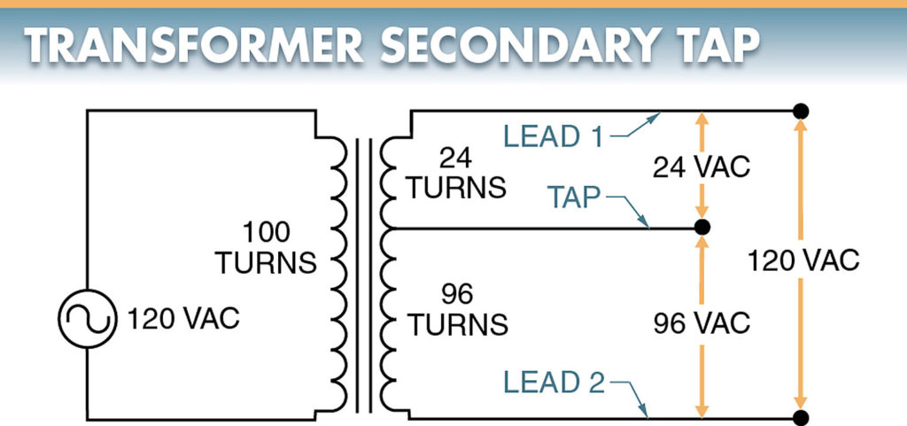
Figure 3. Taps allow different output voltages to be obtained from a transformer.
A tap that splits a secondary in half is referred to as a center tap. A common application of a transformer with a center tap is a distribution transformer.
A distribution transformer is used in residences and businesses to change the high voltage of power company distribution lines to the common 240/120 VAC supply of residences and businesses. See Figure 4.
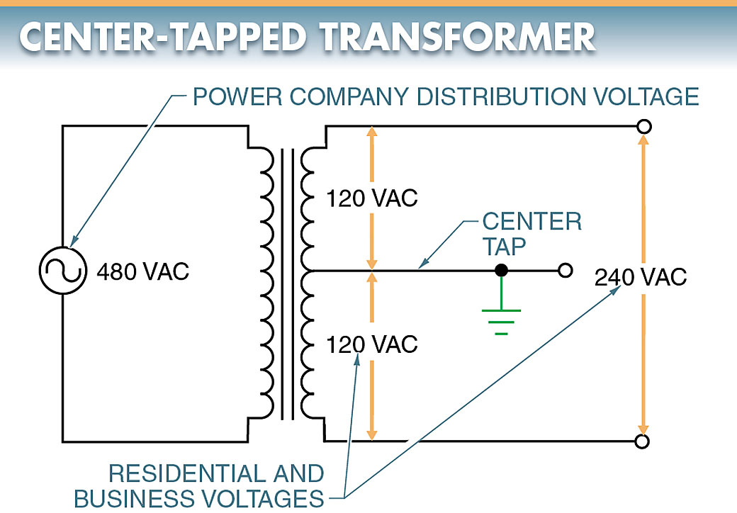
Figure 4. A center-tapped transformer is used to change the high voltage of power company distribution lines to the common 240/120 VAC supply of residences and businesses.
The center tap is connected to earth ground and becomes a common conductor. The voltage across the output lines is 240 VAC. However, the voltage measured between either output line and the center tap is 120 VAC.
The 240 VAC power is used to supply devices in the residence that require a large amount of operating power, such as a central air conditioner, water heater, clothes dryer, and cooking range. These high-power devices run on 240 VAC to allow smaller conductor wires to deliver power to them.
The 120 VAC power is wired to the electrical outlets and lighting system. This provides a much safer level of voltage, which can be used on smaller electrical devices.
Control Transformer Applications
A control transformer is a transformer that is used to step down the voltage to the control circuit of a system or machine. The most common control transformers have two primary coils and one secondary coil. See Figure 5.
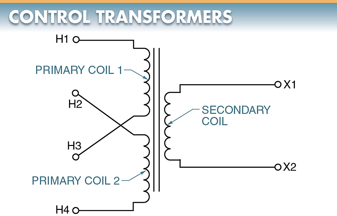
Figure 5. The most common control transformers have two primary coils and one secondary coil.
The primary coils of a control transformer are crossed so that metal links can be used to connect the primaries for either 240 VAC or 480 VAC operation.
In most applications, a control transformer is used to reduce the main or line voltage of 240 VAC or 480 VAC to a control voltage of 120 VAC.
240 V Primary
To obtain a control voltage of 120 VAC from a line voltage of 240 VAC, the two primary coils must be connected in parallel. See Figure 6.
If the primary coils are connected in parallel, the effective turns of the two primary coils are 200, the same as if there were only one primary coil. If the secondary has 100 turns, the turns ratio is 2:1. This means an input voltage of 240 VAC produces an output voltage of 120 VAC.
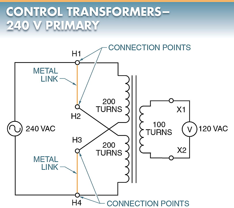
Figure 6. To obtain a control voltage of 120 VAC from a line voltage of 240 VAC, the two primary coils must be connected in parallel.
480 V Primary
To obtain a control voltage of 120 VAC from a line voltage of 480 VAC, the two primary coils must be connected in series. See Figure 7.
If the primary coils are connected in series, the effective turns of the two primary coils are 400, making the turns ratio 4:1. This means an input voltage of 480 VAC produces an output voltage of 120 VAC.
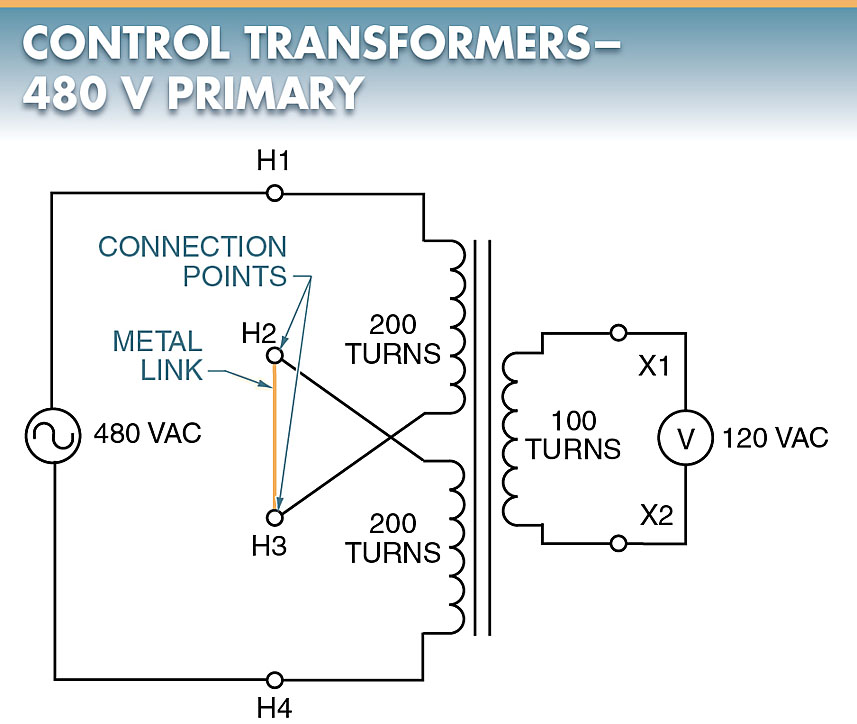
Figure 7. To obtain a control voltage of 120 VAC from a line voltage of 480 VAC, the two primary coils must be connected in series.
Transformer Connections Key Takeaways
In conclusion, understanding transformer connections, secondary taps, and control transformers is essential for ensuring efficient power distribution across residential, commercial, and industrial applications. Single-phase transformer connections provide reliable electrical service for homes, while three-phase transformers support high-power industrial and commercial operations. Transformer secondary taps allow for flexible voltage control, making power distribution adaptable to different load requirements. Additionally, control transformers play a crucial role in reducing high voltages for safer and more efficient control circuits in electrical systems. These configurations and applications are fundamental to modern electrical infrastructure, ensuring stable and optimized power delivery for various needs.