The article covers the working principle, structure, and applications of transformer, explaining how they transfer AC energy through electromagnetic induction. It also discusses transformer efficiency and various losses, including resistive, eddy current, and hysteresis losses.
Transformers are used today in almost every electrical system to either step up, step down, or isolate one voltage level from another. The extensive use of transformers started after what is known in the electrical field as the “War of Currents.”
Thomas Edison believed that the U.S. power distribution system should be DC with DC generators delivering power over a DC distribution system to DC loads.
George Westinghouse believed an AC distribution system would be much better because AC can be distributed over long distances using step-up and step-down transformers.
Westinghouse’s system of AC generators and AC transformers proved to be the best and are now the standard distribution system used around the world.
Because transformers are so important in an electrical system, learning their operating principle and usages is important when designing, installing, or troubleshooting an electrical system.
Transformer Definition
A transformer is an electric device that uses electromagnetism to change voltage from one level to another or to isolate one voltage from another.
Transformers are used in electrical distribution systems to increase or decrease the voltage and current safely and efficiently. For example, transformers are used to increase generated voltage to a high level for transmission across the country and then decrease it to a low level for use by electrical loads. See Figure 1.
Transformers allow power companies to distribute large amounts of power at a reasonable cost. Large transformers are used for power distribution along city streets and in the large manufacturing or commercial buildings.
Large transformers are normally maintained by a power company or by workers who have been specifically trained in high-voltage transformer operation and maintenance.
Technicians often work with small control transformers. Control transformers isolate the power circuit from the control circuit, providing additional safety for the circuit operator.
Transformers are also used in the power supplies of most electronic equipment to step the power line voltage up or down to provide the required operating voltage for the equipment.
A transformer has a primary winding and a secondary winding wound around an iron core. See Figure 2. The primary winding is the coil of a transformer that draws power from the source. The secondary winding is the coil of a transformer that delivers the energy at the transformed or changed voltage to the load.
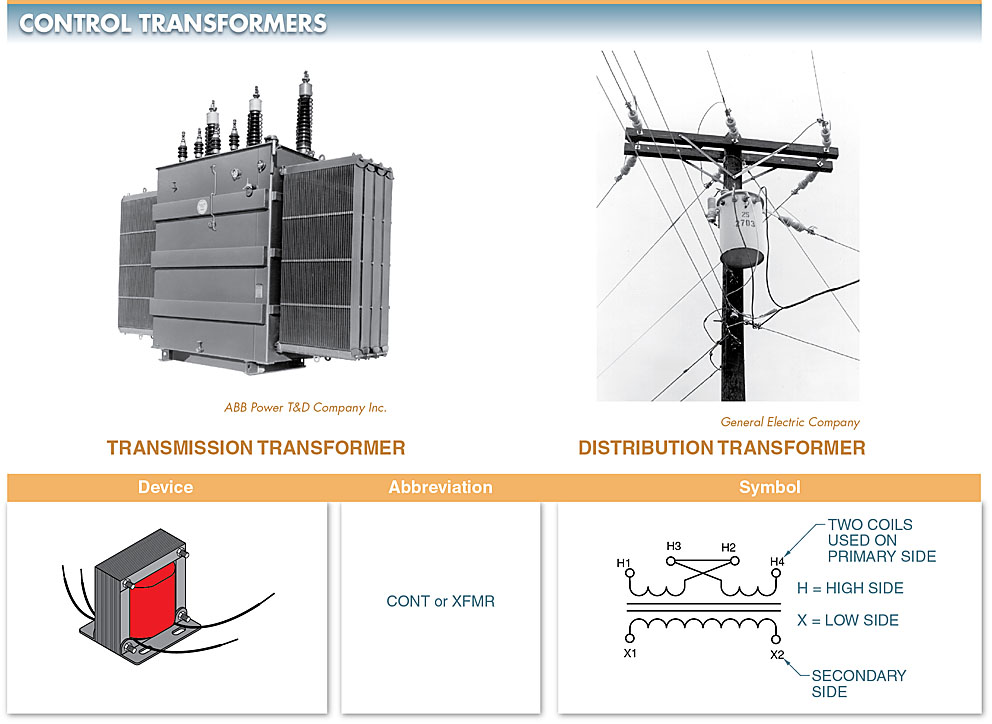
Figure 1. Transformers are used to increase the voltage to a high level for transmission across the country and then decrease it to a low level for use by electrical loads.
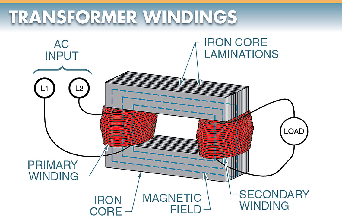
Figure 2. A transformer has a primary winding and a secondary winding wound around an iron core.
Transformer Working Principle
A transformer transfers AC energy from one circuit to another. The energy transfer is made magnetically through the iron core. A magnetic field builds up around a wire when AC is passed through the wire. The magnetic field builds up and collapses each half cycle because the wire is carrying AC. See Figure 3.
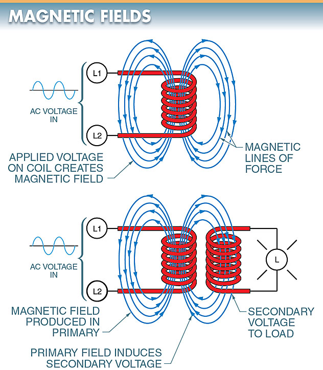
Figure 3. In a transformer, magnetic lines of force created by one coil induce a voltage in a second coil.
The primary coil of the transformer supplies the magnetic field for the iron core. The secondary coil supplies the load with an induced voltage proportional to the number of turns of a conductor cut by the magnetic field of the core.
A transformer is either a step-up or step-down transformer depending on the ratio between the number of turns of the conductor in the primary and secondary sides of the transformer. See Figure 4.
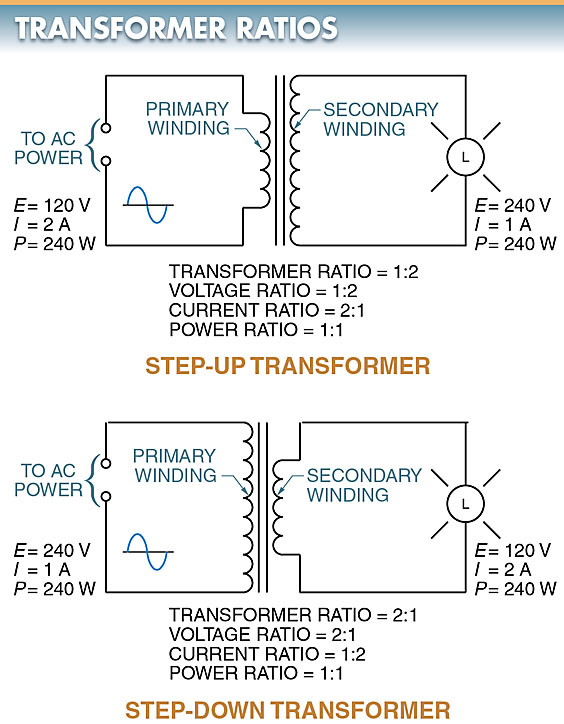
Figure 4. Voltage and current change from the primary to the secondary winding in step-up and step-down transformers.
The turns ratio is the ratio of the number of turns in the primary winding to the number of turns in the secondary winding of a transformer.
If twice as many turns are on the secondary, twice the voltage is induced on the secondary. The ratio of primary to secondary is 1:2, making the transformer a step-up transformer.
However, if only half as many turns are on the secondary, only half the voltage is induced on the secondary. In this case, the ratio of primary to secondary is 2:1, making the transformer a step-down transformer.
In a step-up transformer, a ratio of 1:2 doubles the voltage. This may seem like a gain or a multiplication of voltage without any sacrifice. However, the amount of power transferred in a transformer is equal on both the primary and the secondary, excluding small losses within the transformer.
Because power is equal to voltage times current (P=E×I) and power is always equal on both sides of a transformer, the voltage cannot change without changing the current.
For example, when a voltage is stepped down from 240 V to 120 V in a 2:1 ratio, the current increases from 1 A to 2 A, keeping the power equal on each side of the transformer.
By contrast, when the voltage is stepped up from 120 V to 240 V in a 1:2 ratio, the current is reduced from 2 A to 1 A to maintain the power balance. In other words, voltage and current may be changed for particular reasons, but power is constant.
One advantage of increasing voltage and reducing current is that power may be transmitted through smaller gauge wire, thus reducing the cost of power lines. For this reason, the generated voltages are stepped up very high for distribution across large distances and then stepped back down to meet consumer needs.
Although both the voltage and current can be stepped up or down, the terms step up and step down, when used with transformers, always apply to voltage.
Transformer Losses
Although transformers are very efficient, they are not perfect. Not all of the energy delivered to the primary side by the source is transferred to the secondary load circuit. The majority of the energy lost is lost as heat in the transformer.
The three types of losses in an iron core transformer are resistive, eddy current, and hysteresis losses.
All of these losses make the typical iron core transformer hot when operating under full load. A transformer may be too hot to touch during normal operation, but there should be no odor of burning insulation or varnish or signs of discoloration or smoke. Anyone of these indicates to the technician that the transformer is overloaded or defective.
- Resistive Losses
Resistive losses come from the resistance of the coil winding. When current passes through a winding, the winding heats up and loses energy that could have been transferred to the secondary.
- Eddy Current Losses
Because iron is a fair conductor of electricity, the varying magnetic field that induces a voltage in the secondary of a transformer also induces small voltages in the iron core of the transformer. These small voltages produce eddy currents, which in turn produce heat. This heat also represents a loss because it does no useful work.
Eddy currents are minimized either by making the core out of thin sheets (laminations) that are insulated from each other or by using powdered-iron cores instead of solid blocks of iron.
The insulation between the laminations of a laminated core breaks up the current paths within the core and reduces the eddy currents. This is the same technique used to reduce eddy currents in solenoids.
- Hysteresis Losses
Each time the magnetizing force produced by the primary side of a transformer changes, the atoms of the core realign themselves in the direction of the force. The energy required to realign the iron atoms must be supplied by the input power and is not transferred to the secondary load circuit. The realignment of the iron atoms does not follow the magnetizing force instantaneously but instead lags slightly behind it. This lagging action is called hysteresis.
The degree of hysteresis is a measure of the amount of energy required to realign the iron atoms in the core; the energy lost to do so is called hysteresis loss.
Hysteresis results in heating of the iron core. Because of this and other similarities to mechanical friction, hysteresis is sometimes referred to as magnetic friction. Hysteresis losses are minimized by using high-silicon steel and other alloys in the core.
Transformer Efficiency
In an ideal transformer, energy is transferred from the primary circuit to the secondary circuit and there is no power loss. However, all transformers have some power loss. Most transformers operate with little power loss (normally 0.5% to 8%). The less the power loss, the more efficient the transformer.
The efficiency of a transformer is expressed as a percentage. To calculate the efficiency of a transformer, the following formula is applied:
\[Efficiency=\frac{{{P}_{s}}}{{{P}_{p}}}\times 100\]
Where
Eff = efficiency (in %)
PS = power of secondary circuit (in W)
PP = power of the primary circuit (in W)
For example, what is the efficiency of a transformer that uses 1200 W of primary power to deliver 1110 W of secondary power?
\[Efficiency=\frac{{{P}_{S}}}{{{P}_{P}}}\times 100=\frac{1110}{1200}\times 100=92.5%\]
TECH FACT
In a typical heavy industrial facility, electricity may be delivered directly from a transmission substation to an outside transformer vault. Service-entrance conductors are routed from the outside transformer vault through an outdoor busway to a metered switchboard. Power is then fed through circuit breakers in the panelboard and routed through busways to power distribution panels and busways with plug-in sections to the points of use.
Depending on customer needs, the power distribution system delivers power at standard voltage levels and fixed current ratings to set points such as receptacles.
Transformer Working Key Takeaways
Transformers play a crucial role in modern electrical systems, enabling the efficient transmission and distribution of power across vast distances. Their ability to step up, step down, or isolate voltages ensures the safe and reliable operation of electrical networks, from large-scale power grids to small electronic devices. By minimizing energy losses through advanced core designs and materials, transformers improve efficiency and reduce operational costs. Their widespread applications in industries, commercial buildings, and household appliances highlight their indispensable role in powering the world.