The article covers the behavior of resistors in AC circuits, including the relationship between voltage, current, and power, and the use of RMS values for accurate power calculations. It also discusses the impact of inductance and capacitance in resistive circuits, and methods for mitigating these effects in higher-frequency applications.
The current flowing through a resistor is determined by Ohm’s Law for any instant of time: I = V/R for any part of the cycle. As you should be aware, when the resistance remains the same, the current is directly proportional to the applied voltage. Therefore, the current waveform for a purely resistive circuit is in phase with the voltage curve and Irms = Vrms/R (see Figure 1).
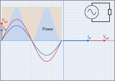
Figure 1 Resistive AC Circuit
Power in a Resistive AC Circuit Formula
If the values V of voltage and I of current are taken at a given instant, then V.I = P is the instantaneous power. By taking the product of V and I for a number of instantaneous values, it is possible to plot a curve of power for each cycle of ac. In Figure 1, only one cycle is shown, as any one cycle represents what any other cycle will do.
The curves for voltage, current and power are shown as generated by a computer program from the mathematics, and the following details should be noted:
| 1. | The power curve is sinusoidal in shape, which agrees with the laws of trigonometry. |
| 2. | There are no negative values of power, as a negative multiplied by a negative becomes positive. |
| 3. | The power curve completes two cycles for each complete cycle of current or voltage. |
| 4. | As the power curve is a sine wave, the area underneath the power curve is identical to the area between the power curve and a line drawn to just touch the peak value of power. |
Therefore the power used is half of what the peak values would have suggested, thus proving that the values for RMS must be 1/√2Vmax and 1/√2Imax.
If values of Irms = 1 A and Vrms = 1 V, power is the rate at which energy is used and therefore there is no RMS value of power, but an absolute value.
\[P={{V}_{rms}}\times {{I}_{rms}}=1\times 1=1W\]
Using maximum values, which are 1.414 times RMS values, gives an answer of twice the actual power used:
\[P={{V}_{\max }}\times {{\operatorname{I}}_{max}}=1.414\times 1.414=2W\]
This result confirms the need to use RMS values when working with alternating current.
For purely resistive circuits, Ohm’s Law and the power law both work using RMS values of voltage and current:
\[\begin{matrix}V=IR & and & P=VI={}^{{{V}^{2}}}/{}_{R}={{I}^{2}}R \\\end{matrix}\]
But with ac, V and I must always be measured in RMS values.
For sinusoidal waveforms only, it should be noted that, if peak values are used to obtain a power rating, the average power value obtained is always half that of the peak power value; that is, average power equals half maximum power.
Substituting maximum values in the power equation gives:
\[{{P}_{avg}}=0.707\times {{V}_{\max }}\times 0.707\times {{\operatorname{I}}_{max}}=0.5{{P}_{\max }}\]
Note that in the following example all three methods of calculating the power are used, to test whether they agree on the same answer.
Purely Resistive AC Circuit
For calculation purposes, resistors on power-line frequencies, such as incandescent lamps, radiators and electric jug elements, can be generally be considered as consisting of ‘pure’ or non-inductive resistance.
Real resistors are often made from a coil of resistance wire which, according to theory, will exhibit some inductance. Normally the value of inductance is so low that it can be ignored, and similarly for capacitance.
At higher frequencies such as found in modern switch-mode power supplies and motor controllers, inductance can become a problem and must either be accounted for in the design stage or special non-inductive resistors used.
The inductive effect can be avoided comparatively easily. Half the resistor is wound on a non-magnetic former in a clockwise direction, and then the other half is wound on in an anticlockwise direction (see Figure 2). The magnetic fields produced around the conductors cancel each other out and so prevent the production of self-induced voltages.
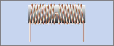
Figure 2 Non-Inductive Resistor
Capacitive effects cannot be neutralized by such direct means; consequently, the aim is to minimize them. The main method used on long-distance transmission lines is to keep them as far apart from each other as is economically possible.
Example 1
A pure resistor of 12 ohms is connected across an ac power supply that generates a pure sine wave of 100 volts peak voltage. What current will flow and what power will be taken?
$$V_{rms}=0.707V_{max}=0.707\times 100=70.7V$$
$$I_{rms}=\frac{V_{rms}}{R}=\frac{70.7}{12}=5.89A$$
$$P=V_{rms}\times I_{rms}=70.7\times 5.89=416.4W$$
$$P=\frac{V^{2}_{rms}}{R}=\frac{70.7^{2}}{12}=416.5W$$
$$P=I^{2}_{rms}\times R=5.89^{2}\times 12=416.6W$$
Resistors in AC Circuits Key Takeaways
In conclusion, understanding the behavior of resistors in AC circuits, including the use of RMS values and the impact of inductance and capacitance, is crucial for accurate power calculations and efficient circuit design. These principles are essential in real-world applications, such as power distribution, switch-mode power supplies, and electric devices, where precise power management and minimizing unwanted inductive or capacitive effects ensure optimal performance and energy efficiency.