Direct current flows in only one direction. Alternating current changes its direction of flow at times in the circuit. In DC, the source voltage does not change its polarity. In AC, the source voltage changes its polarity between positive and negative.
Figure 1 shows the magnitude and polarity of an AC voltage. Starting at zero, the voltage rises to maximum in the positive direction. It then falls back to zero. Then it rises to maximum with the opposite polarity and returns to zero.
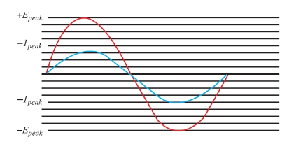
Figure 1. Current and voltage of alternating current.
The current wave is also plotted on the graph. It shows the flow of current and the direction of the flow. Above the zero line, current is flowing in one direction. Below the zero line, the current is flowing in the opposite direction.
The graph in Figure 1 represents instantaneous current and voltage at any point in the cycle. But what is a cycle? A cycle is a sequence or chain of events occurring in a period of time. An AC cycle can be described as a complete set of positive and negative values for AC.
The alternating current in your home changes direction 120 times per second. It has a frequency of 60 cycles per second (60 cps). Frequency, measured in cycles per second, or hertz (Hz), is the number of complete cycles occurring per second. If 60 cycles occur in one second, then the time period for one cycle is 1/60 of a second, or 0.0166 seconds. This is the period of the cycle. Refer again to Figure 1. The maximum rise of the waveform shows the amplitude of the wave, including the peak (highest point) voltage and current.
We learned that induced current in a rotating wire in a magnetic field flowed first in one direction and then in the other direction. This was defined as an alternating current. Two points to remember are:
• The frequency of this cycle of events increases as rotation speed increases.
• The amplitude of the induced voltage depends on the strength of the magnetic field.
Vectors
When solving problems involving alternating currents, vectors are used to depict the magnitude and direction of a force. A vector is a straight line drawn to a scale that represents units of force. An arrowhead on the line shows the direction of the force. The length of the vector shows the magnitude.
The development of an AC wave is shown in Figure 2. This wave is from a single coil armature, represented by the rotating vector, making one revolution through a magnetic field.
Assume that the peak induced voltage is 10 volts. Using a scale in which one inch equals five volts, the vector is two inches, or 10 volts, long. Vectors of this nature are assumed to rotate in a counter- clockwise direction.
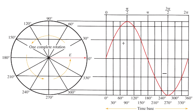
Figure 2. The development of a sine wave. On the left is the rotating phasor. On the right is one cycle of the sine wave.
The time base in Figure 2 is a line using any convenient scale. It shows the period of one cycle or revolution of the vector. The time base is grouped into segments that represent the time for certain degrees of rotation during the cycle.
For example, at 90 degrees rotation, one quarter of the time period is used. At 270 degrees rotation, three quarters of the time period is used. The wave is developed by plotting voltage amplitude at any instant of revolution against the time segment. The developed wave is called a sine wave.
The instantaneous induced voltages are proportioned to the sine of the angle θ (theta) that the vector makes with the horizontal. The instantaneous voltage may then be found at any point of the cycle by making use of the following equation:
$e={{E}_{\max }}\times \sin \theta $
(Notice that the lowercase e was used to represent the instantaneous voltage instead of the usual uppercase. By convention, instantaneous values are represented with lowercase variables.)
To apply this equation, assume that an AC generator is producing a peak voltage of 100 volts. What is the instantaneous voltage at 45 degrees of rotation?
$e=100V\times \sin {{45}^{o}}=100V\times 0.707=70.7V$
Average and RMS Values
A study of the differences between an AC wave and a direct current raises a key question. What is the actual value of the AC wave? The voltage and current vary constantly and reach peak value only twice during a cycle.
Often, the average value of the wave is needed. The average value is the mathematical average of all the instantaneous values during one half-cycle of the alternating current. The formulas for computing the average value from the peak value (max) of any AC waves are:
$\begin{matrix}{{E}_{avg}}=0.637\times {{E}_{\max }} \\or \\{{I}_{avg}}=0.637\times {{\operatorname{I}}_{max}} \\\end{matrix}$
If Eavg or Iavg is known, the conversion to find Emax or Imax can be made using the following equations.
$\begin{matrix}{{E}_{\max }}=1.57\times {{E}_{avg}} \\or \\{{I}_{\max }}=1.57\times {{\operatorname{I}}_{avg}} \\\end{matrix}$
A more useful alternating current value is the effective value. The term effective value comes from scientists finding the AC heating effect equivalent of a direct current.
A specified volume of water was heated using a specified voltage level of dc. Then, the same quantity of water was heated using AC. The AC voltage that produced equivalent heating to the DC voltage was the effective value. The formulas to find the effective value of any AC voltage or current are:
$\begin{matrix}{{E}_{eff}}=0.707\times {{E}_{\max }} \\or \\{{I}_{eff}}=0.707\times {{\operatorname{I}}_{\max }} \\\end{matrix}$
Where Emax and Imax are the peak values of the ac signal. If Eeff or Ieff are known, the conversion to find the peak values can be made by using the following equations.
$\begin{matrix}{{E}_{\max }}=1.414\times {{E}_{eff}} \\or \\{{I}_{\max }}=1.414\times {{\operatorname{I}}_{eff}} \\\end{matrix}$
The effective value is also called the rms value (root mean square). It gets this name because the value represents the square root of the average of all currents squared between zero and maximum of the wave. The currents are squared, so the power produced can be compared to direct current. Watt’s law states: P = I2R.
Using the 0.707 factor, the value of a direct current can be found that will equal the alternating current. For example, a peak AC current of 5 amperes produces the same heating effect in a resistance as a DC current of 3.53 amperes. Plugging the values into the equation:
Ieff = 0.707 × 5 amperes of AC = 3.53 amperes DC
Note that average and effective values can be applied to either voltage or current waves.
Phase Displacement
A few waveforms can be drawn on the same time base to show the phase relationship between them. In Figure 3, waveforms E and I show the voltage and current in a given circuit. The current and voltage rise and fall at the same time. They cross the zero line at the same point. The current and voltage are in phase. The in phase condition only exists in the purely resistive circuit.
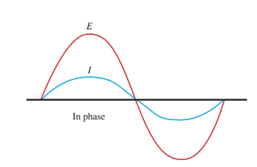
Figure 3. These current and voltage waves are in phase.
Many times the current will lead or lag the voltage, Figure 4. When the current wave leads or lags the voltage wave, the two waves are said to be out of phase. This creates a phase displacement between the two waves. Displacement is measured in degrees. The phase displacement is equal to the angle θ between the two polar vectors.
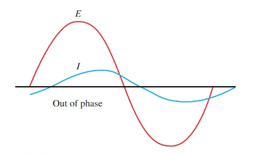
Figure 4. These current and voltage waves are out of phase.
Alternating Current Generator
The ac generator is like the DC generator in many respects with one key exception. The commutator is omitted. The ends of the armature coils are extended out to slip rings. Brushes sliding on the slip rings provide connection to the coils at all times. The current in the externally connected circuit is an alternating current.
In large commercial generators, the magnetic field is rotated and the armature windings are placed in slots in the stationary frame, or stator, of the generator. This method allows for the generation of large currents in the armature while avoiding sending these currents through moving or sliding rings and brushes.
The rotating field is excited through slip rings and brushes by a small DC generator mounted on the same shaft as the rotating magnetic field. This small DC generator is called the exciter. The DC voltage is needed for the magnetic field. Commercial power generators convert many different items (such as moving water, coal, oil, wind, nuclear energy) into electricity. The force mechanism that is used to turn the generator is called the prime mover, Figure 5.
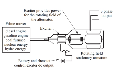
Figure 5. The prime mover, exciter, and three-phase alternator share a common rotating shaft. The exciter provides electrical energy for the alternator.
The Alternator or AC Generator
The AC generator (also called an alternator) is used in the charging system of all U.S. automobiles. Figure 6 shows the inside of the unit, including a built-in voltage regulator to control output. The output is rectified from alternating current to direct current for charging the battery and other electrical devices in the car.
Manufacturers say the alternator has some advantages over the DC generator. These advantages include higher output at lower speeds, as well as trouble-free service.
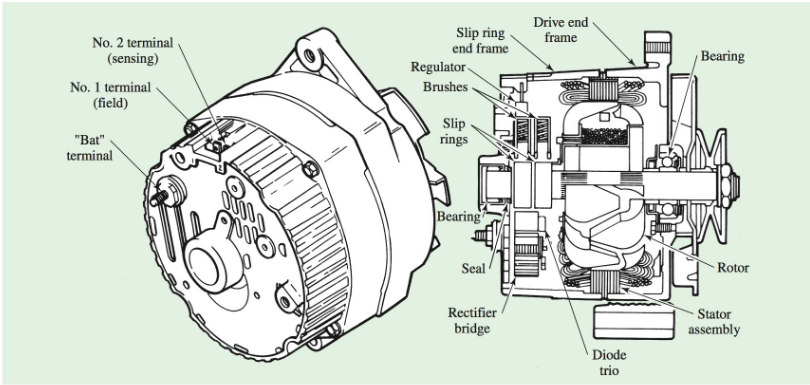
Figure 6. A typical AC generator (alternator) is shown in external and cutaway views.

