The article provides an overview of different types and working of DC generator, focusing on their excitation methods and working principles. It covers separately excited and self-excited generators, including shunt, series, and compound types, along with their voltage and current regulation mechanisms.
There are a number of different types of DC generators. Several of these generator types will be discussed briefly. Study their similarities as well as their differences. DC Generators can be distinguished by their method of excitation. Self-excited generators can be separated further into the categories of shunt, series, and compound.
One feature that separates DC generators is the excitation method, the method that is used to start the generator running. Some generators require a separate power source during the starting of the generator. These are called separately excited field DC generators. Other generators use the generator’s own leftover magnetism in place of that power source. These are self-excited DC generators.
Separately Excited Field DC Generator
Generator output is determined by the strength of the magnetic field and the speed of rotation. Field strength is measured in ampere-turns. So, an increase in current in the field windings will increase the field strength.
Output voltage is in direct proportion to field strength times the speed of rotation. Therefore, most output regulating devices depend on varying the current in the field.
The field windings can be connected to a separate, or independent, source of DC voltage, Figure 1. This is the separately excited field generator. With the speed constant, the output may be varied by controlling the exciting voltage of the DC source. This is done by inserting resistance in series with the source and field windings.
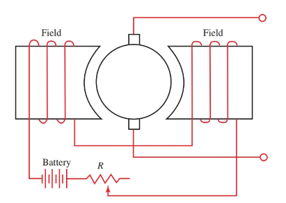
Figure 1. A separately excited generator
Self-Excited DC Generator
A self-excited DC generator uses no separate source of voltage to excite the generator field winding.
The self-excited generator produces a small voltage when the armature windings cut across a weak magnetic field. This weak magnetic field is caused by magnetism left over in the pole shoes or field coil cores after the voltage and current have ceased to flow. The magnetism left in a magnet after the magnetizing force has been removed is called residual magnetism.
Look ahead to the diagram of the shunt generator shown in Figure 2. A residual magnetic field will cause a small voltage to be produced as the armature conductors rotate past the field poles. The small voltage produced will, in turn, cause the current to increase through the field poles. An increase in field pole magnetism will cause a further increase in output voltage.
The relationship of the current produced by the armature directly increasing the amount of magnetism in the field poles is how the self-excited generator works. The magnetism produced by the armature voltage will increase until the field poles reach saturation, the point where the poles cannot contain any more magnetic lines of force.
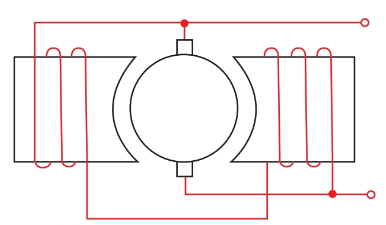
Figure 2. A shunt generator.
Shunt Generator
The shunt generator derives its name from the way the field pole coils are connected in parallel to the armature, Figure 2. Another way of saying parallel is the term shunt.
The field windings consist of many turns of small wire. They use only a small part of the generated current to produce the magnetic field in the pole’s windings. The total current generated must, of course, be the sum of the field excitation current and the current delivered to the load. Thus, the output current can be thought of as varying according to the applied load.
The field flux does not vary to a great extent. Therefore, the terminal voltage remains constant under varying load conditions. This type of generator is considered a constant voltage machine.
All machines are designed to do a certain amount of work. If overloaded, their lives are shortened. As with any machine, the life of a generator can be shortened by an overload condition.
When overloaded, the shunt generator terminal voltage drops rapidly. Excessive current causes the armature windings to heat up. The heat can cause the generator to fail by destroying the thin coat of insulation covering the armature wires.
Series Generator
The series generator is so named because its field windings are wired in series with the armature and the load. Such a generator is sketched in Figure 3.
A series winding by itself will provide a fluctuating voltage to the generator load. As the current increases or decreases through the load, the voltage at the generator output terminals will greatly increase or decrease. Because of the wide difference in output voltage, it is not a very practical generator to use if the load varies.
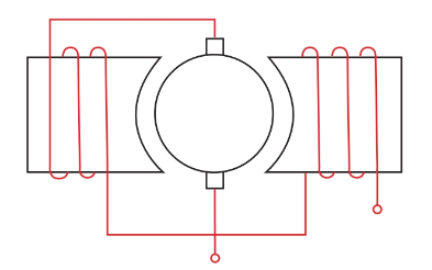
Figure 3. A series wound generator.
Compound Generator
The compound generator uses both series and shunt windings in the field.
The series windings are often a few turns of large wire. The wire size of the series winding is usually the same size as the armature conductors. These windings must carry the same amount of current as the armature since they are in series with each other.
The series windings are mounted on the same poles with the shunt windings. Both windings add to the field strength of the generator field poles. If both act in the same direction or polarity, an increase in load causes an increase of current in the series coils. This increase in current would increase the magnetic field and the terminal voltage of the output. The fields are said to be additive. The resulting field would be the sum of both coils. However, the current through the series winding can produce magnetic saturation of the core. This saturation results in a decrease of voltage as the load increases.
The way terminal voltage behaves depends on the degree of compounding. A compound generator that maintains the same voltage either at no-load or full-load conditions is said to be a flat-compounded generator. An over compounded generator, then, will increase the output voltage at full-load. An under compounded generator will have a decreased voltage at full-load current.
A variable load may be placed in parallel with the series winding to adjust the degree of compounding. Figure 4 shows schematic diagrams of the shunt, the series, and the compound generator.
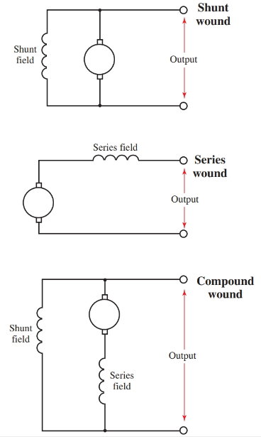
Figure 4. Compare these wiring diagrams of the shunt, series, and compound generator.
Voltage and Current Regulation
The regulation of a power source, whether a generator or a power supply, can be defined as the percentage of voltage drop between no-load and full-load. Mathematically, it can be expressed:
\[\frac{{{\text{E}}_{\text{no-load}}}\text{-}{{\text{E}}_{\text{full-load}}}}{{{\text{E}}_{\text{full-load}}}}\text{ }\!\!\times\!\!\text{ 100=Percentage Regulation}\]
To explain this formula, assume that the voltage of a generator with no-load applied is 100 volts. Under full- load the voltage drops to 97 volts. Filling in the equation:
\[\frac{\text{100V-97V}}{97V}\text{ }\!\!\times\!\!\text{ 100=3}\text{.1 Percent}\]
In most uses, the output of the generator should be maintained at a fixed voltage value under varying load conditions.
The output voltage of the generator depends upon the field strength. The field strength depends upon the field current. Current, according to Ohm’s law, varies inversely with resistance. Therefore, a device that would vary the resistance in the field circuit would also vary the voltage output of the generator. This regulator is shown in Figure 5. It was often used in automobiles.
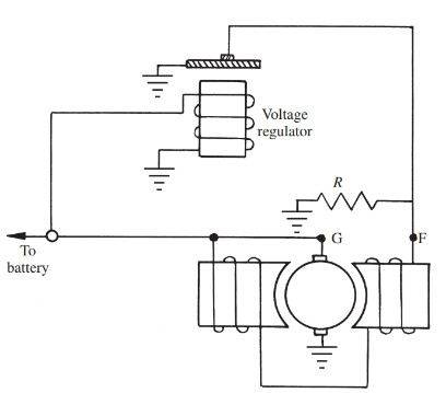
Figure 5. Circuit Diagram for a generator voltage regulator.
The generator output at terminal G is joined to the battery and the winding of a magnetic relay. The voltage produced by the generator causes a current to flow in the relay coil. If the voltage exceeds a preset value, the increased current provides enough magnetism to open the relay contacts.
Notice that the generator field is grounded through these contacts. When they open, the field current must pass through resistance R to ground. This resistance reduces the current, which reduces the field strength and reduces the terminal voltage. When the terminal voltage is reduced, the relay contact closes, permitting maximum field current. The terminal voltage rises. In operation, these contact points vibrate. They alternately cut resistance in and out of the field circuit and maintain a constant voltage output of the generator.
Mechanical-magnetic relays have served this purpose for many years. Now, however, electronic devices are being used on cars. An electronic regulator using an integrated circuit for the switching functions is shown in Figure 6.
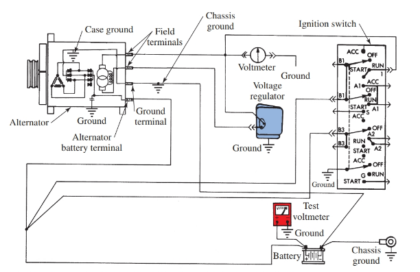
Figure 6. Electrical voltage regulators are used on all new cars.
DC Generator Types & Working Key Takeaways
In conclusion, understanding the different types and working of DC generator and their excitation methods is crucial for various practical applications. These generators play a vital role in industries such as power generation, automotive systems, and backup energy solutions. Separately excited generators provide precise voltage control, making them suitable for laboratory and industrial applications, while self-excited generators, including shunt, series, and compound types, are widely used in commercial and transportation sectors due to their self-sustaining operation. Effective voltage and current regulation mechanisms ensure reliable performance under varying load conditions, making DC generators essential for stable and efficient power supply systems.