The article provides a general overview of capacitance, explaining its definition, working principle, and the factors that affect it. It also covers key safety considerations, voltage ratings, and the formula used to calculate capacitance in electronic circuits.
Definition: Capacitance is a property that opposes any change in voltage. A capacitor is a device that temporarily stores an electric charge.
A capacitor accepts or returns this charge in order to maintain a constant voltage. Schematic symbols that are used to represent a capacitor are shown in Figure 1.
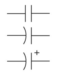
Figure 1. Schematic symbols for the capacitor.
The capacitor is made of two plates of conductive material, separated by insulation. This insulation is called a dielectric, Figure 2.
In the figure, the plates are connected to a dc voltage source. The circuit appears to be an open circuit because the plates do not contact each other. However, the meter in the circuit will show some current flow for a brief period after the switch is closed.
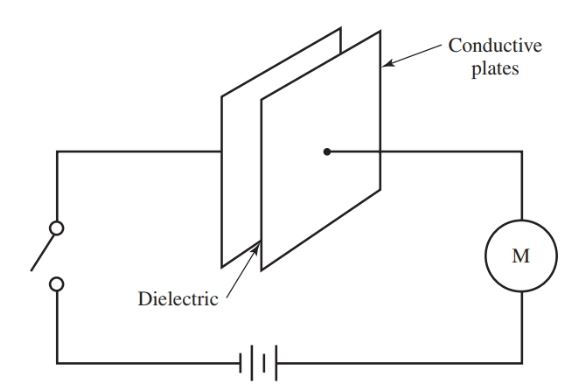
Figure 2. A basic form of a capacitor.
In Figure 3, as the switch is closed, electrons from the negative terminal of the source flow to one plate of the capacitor. These electrons repel electrons from the second plate (like charges repel), which are then drawn to the positive terminal of the source. The capacitor is now charged to the same potential as the source and is opposing the source voltage.
If the capacitor is removed from the circuit, it will remain charged. The energy is stored within the electric field of the capacitor. Once the capacitor is fully charged, current ceases to flow in the circuit.
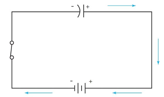
Figure 3. The capacitor charges to the source voltage.
It is important to remember that in the circuit in Figure 3, no electrons flowed through the capacitor. This is because a capacitor blocks direct current. However, one plate did become negatively charged and the other positively charged. A strong electric field exists between them.
Insulating or dielectric materials vary in their ability to support the electric field. This ability is known as the dielectric constant of the material.
The constants of various materials are shown in Figure 4. These numbers are based on comparison with the dielectric constant of dry air. The constant for dry air has been assigned as 1.
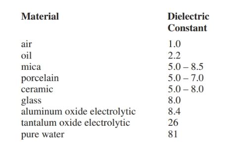
Figure 4. Dielectric constants. Larger numbers are better able to support electric fields.
Capacitor Working Voltage
The dielectrics used for capacitors can only withstand certain voltages. If this voltage is exceeded, the dielectric will break down and arcing will result. This maximum voltage is known as the working voltage (WV).
Exceeding the working voltage can cause a short circuit and can ruin other parts of the circuit connected to the dielectric.
Increased voltage ratings require special materials and thicker dielectrics. When a capacitor is replaced, check its capacitance value and dc working voltage.
When a capacitor is used in an ac circuit, the working voltage should safely exceed the peak ac voltage. For example, a 120-volt effective ac voltage has a peak voltage of 120 V × 1.414 = 169.7 volts. Any capacitors used must be able to handle 169.7 volts.
Capacitance Calculation Formula
Capacitance is determined by the number of electrons that can be stored in the capacitor for each volt of the applied voltage. Capacitance is measured in farads (F). A farad represents a charge of one coulomb that raises the potential one volt. This equation is written:
\[C=\frac{Q}{E}\]
Where C is the capacitance in farads, Q is the charge in coulombs, and E is the voltage in volts.
Capacitors used in electronic work have capacities measured in microfarads (1/1,000,000 F) and Pico farads (1/1,000,000 of 1/1,000,000 F). Microfarad is commonly written as μF or sometimes written as mfd. Picofarad is written as pF. Nano farad is not a common measurement of capacitance.
A conversion chart for these units is shown in Figure 5.
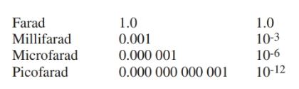
Figure 5. Prefixes used with the farad. Take special note that the prefix nano is missing. Nano farad is not a standard rating size for a capacitor.
Capacitance is determined by:
- The material used as a dielectric. (The larger the dielectric constant, the greater the capacitance.)
- The area of the plates. (The larger the plate area, the greater the capacitance.)
- The distance between the plates. (The smaller the distance, the greater the capacitance.)
- These factors are related in the mathematical formula:
\[C=0.225\times \frac{KA\left( n-1 \right)}{d}\]
Where C is the capacitance in Pico farads, K equals the dielectric constant, A equals the area of one side of one plate in square inches, d equals the distance between plates in inches, and n equals the number of plates.
This formula illustrates the following facts:
- Capacity increases as the area of the plates increase, or as the dielectric constant increases.
- Capacity decreases as the distance between plate’s increases.
A lesson in Safety
Many large capacitors in TVs and other electronic equipment retain their charge for a long time after power is turned off. Discharge these capacitors by shorting terminals to the equipment’s chassis with an insulated screwdriver.
If capacitors are not discharged, the voltages can destroy test equipment, and persons working on the equipment can receive a severe shock!
Capacitance Key Takeaways
Understanding capacitance and the principles behind capacitor operation is essential for designing and maintaining electronic circuits. Capacitors play a critical role in energy storage, voltage regulation, signal filtering, and power conditioning—making them indispensable in a wide range of applications, from everyday consumer electronics to complex industrial systems.