The article covers the series and shunt type ohmmeters, explaining their circuit configurations, working principles, and usage. It also discusses ohmmeter scales, calibration procedures, and safety precautions to ensure accurate resistance measurements.
Definition: A meter used to measure the value of an unknown resistance is called an ohmmeter.
The same meter movement that was used in the voltmeter and ammeter can be used for the ohmmeter. A voltage source and a variable resistor are added to the ohmmeter’s circuit.
Series Type Ohmmeter Working Principle
A series type ohmmeter is shown in Figure 1.
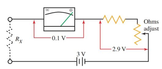
Figure 1. Circuit diagram of a series type ohmmeter.
A three-volt battery is used as the source for the ohmmeter. The battery is built into the meter case. The meter movement permits only 0.1 volts for a current of 0.001 amps for full-scale deflection. Therefore, a multiplier resistor is placed in series with the meter coil to reduce the voltage applied to the meter coil.
\[{{R}_{M}}=\frac{E}{I}=\frac{2.9V}{0.001A}=2900\Omega \]
The 2900 ohm multiplier resistor, plus the meter coil resistance, is equal to 3000 ohms. Part of this resistance is made up of a variable resistor to allow the total resistance to vary.
- Because temperature changes or weak batteries can affect the total resistance of the circuit, the ohmmeter must be calibrated (adjusted for zero resistance) in order to ensure the most accurate reading possible.
- The knob used for adjusting the pointing needle position to zero is usually marked “Zero Adjust,” or with an omega (Ω) symbol near it.
- To use the ohmmeter, first short the test leads together. This applies 0 ohms across the meter. Adjust the ohms adjustment knob until the needle points at zero.
- The needle should deflect from its position at rest on the left to the zero resistance indication on the right side of the scale. If the needle does not deflect, it is possible that the battery is dead or extremely weak.
- After the ohmmeter has been calibrated to read zero ohms when the leads are shorted, you can make a reading of an unknown resistance by placing the unknown resistance between the test leads.
Caution:
Before connecting an ohmmeter to any electrical circuit to read an unknown value, be sure that the circuit is not energized.
An energized circuit will damage the meter and can be harmful to you. The electrical energy in a circuit is not needed to operate the meter movement coil as it is when using a voltmeter or an ammeter.
The batteries inside the case provide the source of power for the ohmmeter. Connecting the ohmmeter to an energized circuit will apply the circuit voltage directly to the coil and battery, which can result in damage to the meter and possible harm to you.
Shunt Type Ohmmeter Working Principle
A shunt ohmmeter is connected as shown in Figure 2. In this circuit, the unknown resistance RX is shunted (connected in parallel) across the meter. Low values of RX cause lower currents through the meter. High values of RX cause high meter currents.
When the ohmmeter is connected in the shunt position, the indicating needle deflects from right to left in the manner of the ammeter and voltmeter. Zero resistance is on the left. The scale increases from left to right.
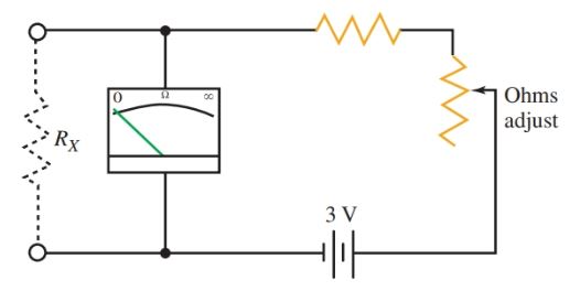
Figure 2. Circuit diagram of a shunt ohmmeter. Note that the meter reads in the opposite direction of other ohmmeters.
Ohmmeter Scales
The resistance value is indicated on the ohms scale, which is a nonlinear scale. A nonlinear scale has markings that are not evenly spaced.
The nonlinear scale factor increases as the needle travels from zero resistance to infinite resistance. In Figure 3, a typical ohmmeter scale is represented.
On the right side of the scale is zero. On the left side is infinity (∞). An infinity reading means that the resistance value is so high that it exceeds the capabilities of the ohmmeter to read it.
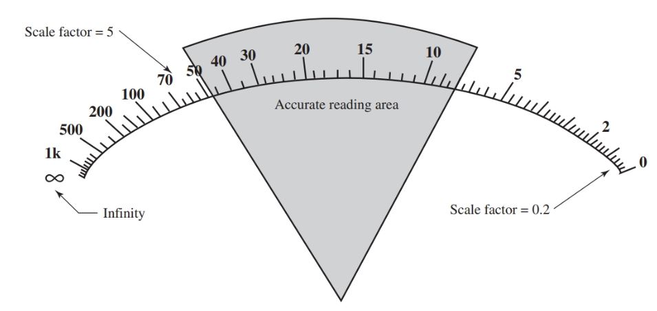
Figure 3. The ohmmeter scale is a nonlinear scale. The scale factor varies in value along the scale. The most accurate readings are taken along the shaded area (the middle 1/3) of the scale.
Notice how the scale factor changes along the ohmmeter scale. On the right side, the small marks between the numbers 0 and 2 represent 0.2 ohms each. On the left side, between the 50 and 70-ohm marks, the small marks represent 5 ohms each.
To take accurate readings of unknown resistance values, it is recommended that the range selector switch is changed until the reading falls in the mid-third of the scale.
An ohmmeter comes with a selection of ranges that can be changed by rotating the selector switch. Typical range values are R × 10, R × 100, R × 1k, and R × 10k. These markings mean that the reading indicated on the ohm scale should be multiplied by 10, 100, 1000, and 10,000 respectively.
Ohmmeter Key Takeaways
In conclusion, ohmmeters play a crucial role in measuring resistance accurately, making them indispensable in electrical and electronic applications. Their ability to diagnose circuit conditions, test components, and ensure proper functioning of electrical systems makes them valuable tools for engineers, technicians, and hobbyists. The series and shunt ohmmeter configurations allow for versatile resistance measurements, while the nonlinear scale ensures precision across different ranges. Proper calibration and safe usage are essential to prevent damage and ensure reliable readings. Whether troubleshooting electrical circuits, verifying component values, or maintaining electronic devices, ohmmeters are fundamental instruments that enhance efficiency and safety in electrical work.