The article covers the fundamental principles of DC motors, including their construction, working mechanism, and operation based on magnetic interactions. It also discusses practical motor applications, counter-electromotive force, and overload protection methods to ensure safe and efficient motor operation.
One of the most important developments in the field of electricity is the electric motor. The electric motor converts electrical power into rotating mechanical power.
Motors are used for such items as refrigeration and air conditioning, food mixers, vacuum cleaners, grinders, pumps, power bench saws, lathes, various wood and metal machines, as well as hundreds of other useful machines.
DC Motor Operation (Working Principle)
The DC motor is simply an application of magnetic principles. Motor rotation depends on the interaction of magnetic fields. You will recall that the laws of magnetism state that:
Like poles repel each other.
Unlike poles attract each other.
Or
A north pole repels a north pole. A south pole repels a south pole.
But
North and south poles attract each other.
The theory of the simple DC motor is detailed in Figures 1 through 9. Figures 1 and 2 diagram the basic parts, the fields and the armature. Figures 3 and 4 put the motor parts together. Figures 5 through 9 take you through the motor action. Examine these figures.
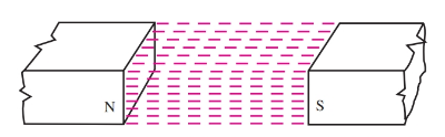
Figure 1. A magnetic field exists between the north and south poles of a permanent magnet.
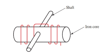
Figure 2. An electromagnet is wound on an iron core and the core is placed on a shaft so it can rotate. This assembly is called the armature
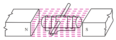
Figure 3. The armature is placed in the permanent magnetic field
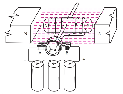
Figure 4. The ends of the armature coil are connected to semicircular sections of metal called commutators. Brushes contact the rotating commutator sections and energize the armature coil from an external power source. (Recall that the polarity of the armature electromagnets depends on the direction of the current flowing through the coil.) A battery is connected to the brushes. Current flows into brush A to commutator section A, through the coil to section B, and back to the battery through brush B, completing the circuit. The armature coil is magnetized as indicated in the sketch
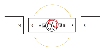
Figure 5. The north pole of the armature is repelled by the north pole of the field magnet. The south pole of the armature is repelled by the south pole of the field magnet. The armature turns one quarter revolution, or 90 degrees.
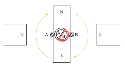
Figure 6. The north pole of the armature is attracted by the south pole of the field magnet. The south pole of the armature is attracted by the north pole of the field magnet. The armature turns another quarter turn. It has now turned one-half revolution.
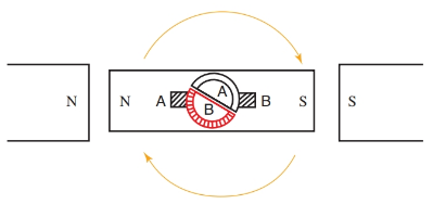
Figure 7. As the commutator sections turn with the armature, section B contacts brush A and section A contacts brush B. The current now flows into section B and out section A. The current has been reversed in the armature due to commutator switching action. The current reversal changes the polarity of the armature, so that unlike poles are next to each other.
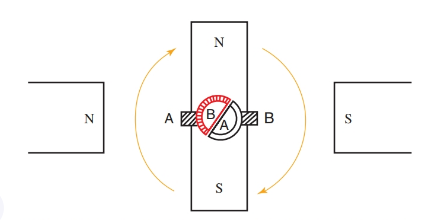
Figure 8. Like poles repel each other and unlike poles attract each other. The armature turns another quarter turn.
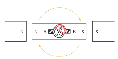
Figure 9. Unlike poles attract each other and the armature turns the last quarter turn, completing one revolution. The commutator and brushes are now lined up in their original positions, which causes the current to reverse in the armature again. The armature continues to rotate by repulsion and attraction. The current is reversed at each one-half revolution by the commutator.
The construction of a simple DC motor is very similar to a DC generator. In fact, a DC generator and motor are often interchangeable in use. In these cases, they are referred to as DC machines.
To make the motor more powerful, permanent field magnets can be replaced by electromagnets called field windings. The field winding is placed over a soft iron pole piece. It consists of many turns of enamel-covered copper wire. Like the generator, the field windings can have an independent source of voltage connected to them. Or, the field windings can be connected in series or parallel with the armature windings to a single voltage source, examine Figure 10.
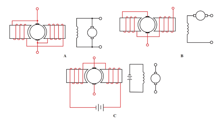
Figure 10. Sketches and schematic diagrams of field winding connections. A–Shunt wound motor is connected in parallel. B–Series wound motor. C–Separately excited field motor.
Construct a trial motor, Figure 11. Connect the motor first in series, then in parallel as a shunt motor. Compare the speed and power of the two motors.
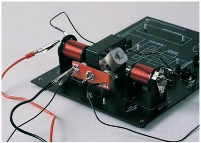
Figure 11. Examine the trial motor with series and parallel connections.
A Practical Motor
In industry, motors are made in a slightly different manner than discussed. Rotational force comes from the interaction between the magnetic field found around a current-carrying conductor and a fixed magnetic field. A conductor carrying a current has a magnetic field around it. The direction of the field depends on the direction of the current. When this conductor is placed in a fixed magnetic field, the interaction between the two fields causes motion. Study Figures 12 through 16.
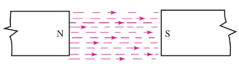
Figure 12. A magnetic field exists between the poles of a permanent magnet. The arrows indicate the direction of the field.
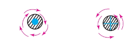
Figure 13. A current carrying conductor has a magnetic field; its direction depends on the direction of the current. Use the left hand rule to determine direction.
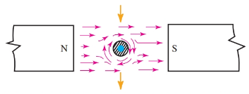
Figure 14. The field around the conductor flows with the permanent field above the conductor but opposes the permanent field below the conductor. The conductor will move toward the weakened field.
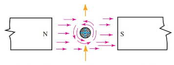
Figure 15. The current has been reversed in the conductor, causing the conductor field to reverse. Now the field is reinforced below the conductor and weakened above the conductor. The conductor will move up.
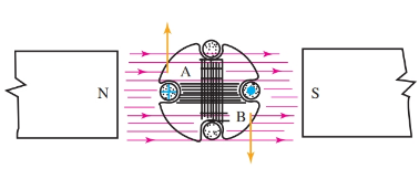
Figure 16. The single conductor is replaced by a coil of conductors wound in the slots of an armature core. Notice how the interaction of the two fields will produce rotation. Coil side A moves up and coil side B moves down. The rotation is clockwise.
Armature coils on industry motors are connected to commutator sections, as in the trial motor. The theory of operation is similar. A practical motor has several armature coils wound in separate slots around the core. Each coil has a commutator section. Increasing the number of field poles gives the motor greater power.
A four-pole motor is sketched in Figure 17. The current divides into four parts. The current flowing in windings under each field pole produces rotation. This then increases the turning power, or torque, of the motor.
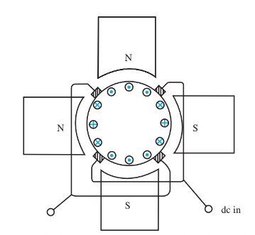
Figure 17. The torque of the motor is increased by adding armature coils and field coils.
Counter-electromotive Force
When a conductor cuts through a magnetic field, voltage is induced in the moving conductor. And while a motor is meant to convert electrical energy into mechanical energy, when the armature begins to rotate, the motor also becomes a generator.
The generated electrical force that opposes the applied emf is called counter-electromotive force. Counter-electromotive force is often written as counter emf or c-emf. It is a result of the generator action of the motor. If the motor were connected to a prime mover and rotated in the same direction as the DC motor, it would produce a voltage with the opposite polarity. See Figure 18.
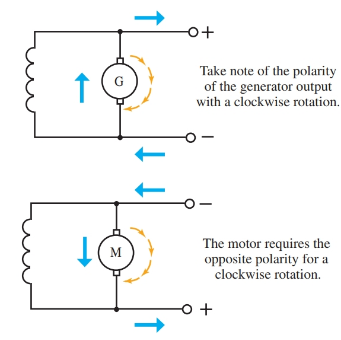
Figure 18. The generator and the motor are rotating clockwise. The DC generator develops a polarity opposite of the motor polarity for the same clockwise rotation. This is the basis of counter emf.
The counter emf magnitude increases as the rotational speed and field strength increase. Therefore:
\[\text{Counter emf=Speed }\!\!\times\!\!\text{ Field Strength }\!\!\times\!\!\text{ K}\]
Where K equals some constant. This constant will vary in different motors. It is affected by things such as the number of windings. The actual effective voltage when applied to the windings in the armature must equal:
${{E}_{source}}-{{E}_{counter}}={{E}_{armature}}$
The current flowing in the armature windings at any given instant can be found using Ohm’s law when the ohmic resistance of the windings is known:
\[{{I}_{armature}}=\frac{{{E}_{armature}}}{{{R}_{armature}}}\]
It is important to note that, as rotation of the motor armature slows down, less counter emf is generated. As a result of less counter emf being produced, there will be an increase in the current through the armature circuit. The current will continue to increase until the motor stops rotating as it does when physically overloaded.
When the motor stalls, maximum current through the armature circuit is limited only by the resistance of the armature. This condition results in extremely high current values. A DC motor must be properly protected against overload conditions.
Overload Protection
Overload protection can be provided through one of several methods. The method used depends upon the size, type, and application of the motor. The circuit feeding power to the motor is usually protected by a fuse or circuit breaker.
A fuse or circuit breaker provides the best method of protection against damage from short circuit or locked rotor conditions. Locked rotor is a term that means the rotor is not turning because of a physical impedance while the power is applied to the motor.
Actual overload protection is usually provided by a thermo-overload. A thermo-overload device is a simple ratch wheel device held in place by a metal alloy such as solder. When the overload condition generates sufficient current flow to melt the solder, the wheel is free to rotate, causing the circuit to open. This allows the motor to safely shut down before any damage occurs to the equipment or personnel. See Figure 19.
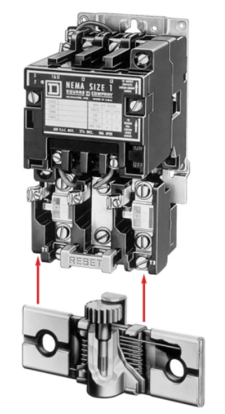
Figure 19. The thermo-overload mounts to the bottom of a motor starter and provides protection for motor overloads
Another type of overload protection is a bimetallic overload device. Bimetallic overload devices contain a bimetallic strip with contacts at each end A bimetallic strip has two layers, with each layer made of a different metal.
Current flows through the bimetallic strip and through the contacts. When the current reaches a set level, the bimetallic strips bend far enough that the contacts separate, opening the circuit. Because each of the two metals expand at different rates, the bimetallic strip bends. Once the bimetallic strip cools, it returns to its original shape and closes the contacts once more. See Figure 20.
According to the National Electric Code, DC motors over one horsepower should be protected by a fuse or a breaker that is no more than 150 percent of the full-load current. The size of the conductor feeding the motor should be able to carry at least 125 percent of the full-load current.
The thermo-overload device is sized closely to the maximum full-load current rating of the motor. It is usually sized at 115 to 125 percent of the full- load current depending on the exact type of motor and its application.
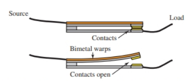
Figure 20. The two different metals expand to different lengths, causing an open circuit
Commutation and Interpoles
As the motor armature rotates, the current in the armature windings routinely reverses. This is caused by commutator action. Due to the self-inductance of the windings, however, the current does not instantly reverse. This results in sparking at the commutator brushes.
There are a number of methods for preventing these sparks. Changing the position of the brushes is one method. With this method, the brushes are moved slightly against the direction of rotation, and the counter emf is used to induce the previous pole. The counter emf opposes the self-induction caused by the decreasing current in the coil. Sparking is eliminated.
This method, however, is not a practical method for preventing sparks on large motors used in a varying load condition. As the load varies on the motor, the brush position must be changed by hand. Instead, larger motors use interpoles to reduce the sparking. An interpole is a smaller field pole placed midway between main field poles, Figure 21.
The interpole has the same polarity as the main field poles and follows the main pole in direction of rotation. Interpoles are also called commutating poles.
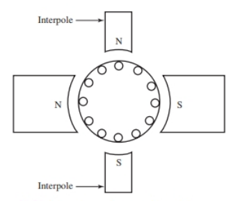
Figure 21. Interpoles reduce sparking at the commutator.
A counter emf is developed as the armature passes the interpole. This counter emf overcomes the emf caused by self-induction in the armature windings. The windings of the interpole are connected in series with the armature and carry the armature current. Thus, interpole field strength varies as the load varies, and it provides automatic control of commutator sparking.
Speed Regulation
Many motors are designed for special purposes. Some develop full power under load, while others must be brought up to speed before the load is applied.
When the speed for a motor is determined on the job, the motor should maintain that speed under varying load conditions.
A ratio of the speed under no-load conditions to the speed under full-load can be expressed as a percentage of the full-load speed. This is called the percent of speed regulation. The equation is written:
\[\text{Percentage of Speed Regulation=}\frac{\text{No-Load Speed-Full-Load Speed}}{\text{Full-Load Speed}}\text{ }\!\!\times\!\!\text{ 100 Percent}\]
A low-speed regulation percentage means that the motor operates at a somewhat constant speed, regardless of load applied.
DC Motor Types Key Takeaways
DC motor play a crucial role in various applications, making them an essential part of modern industries and everyday devices. Their ability to efficiently convert electrical energy into mechanical motion enables their use in household appliances, industrial machinery, and automation systems. The principles of magnetism and counter-electromotive force ensure smooth operation, while overload protection mechanisms enhance safety and reliability. Understanding the working principles and applications of DC motor is vital for optimizing performance, improving energy efficiency, and ensuring the longevity of electrical systems. Their widespread use across different sectors highlights their importance in advancing technology and industrial progress.