The article provides an overview of various transformer applications, including autotransformers, circuit breakers, lighting ballasts, coupling transformers, isolation transformers, and automobile ignition coils.
There are quite a number of special transformer applications. The following text details only a few of these applications.
Auto Transformers
The common transformer consists of two windings: primary and secondary. While the two windings are not physically joined, a magnetic coupling exists between them. The electrical separation between the windings is called isolation. Isolation reduces the chance for shock.
An autotransformer has only one winding. The primary and secondary windings are physically joined at some point. There is no isolation. This condition increases the risk of electrical shock. However, the auto- transformer is most often used in relatively low-voltage applications.
Autotransformers can be of either the step-up or step-down type, Figure 1.
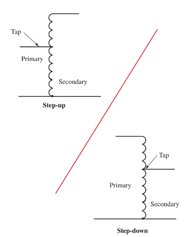
Figure 1. Autotransformers are less costly than regular transformers. Taps may be made variable so that the secondary voltage can be changed.
Induction Circuit Breaker
One common use of the induction coil is in circuit breakers. Circuit breakers use an inductor to trigger a switch to shut off the current in a circuit.
Current traveling through the coil of a circuit breaker produces a magnetic field. When a certain level of current is reached, the strength of the magnetic field breaks the circuit. The circuit must be reset manually.
Many circuit breakers are designed to protect equipment or prevent fires. The circuit breaker in the power strip in Figure 2 is designed to prevent fires caused by a short in an electrical device. The button on the side allows the breaker to be reset.
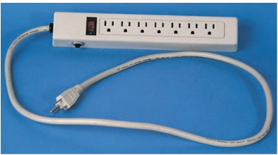
Figure 2. Circuit breakers in power strips use inductors to protect equipment, property, and people.
Lighting Ballast
Electrical discharge lighting systems such as fluorescent lighting and mercury vapor use a special classification of transformer known as a ballast.
A ballast serves two purposes in electric discharge lighting. The ballast is used to start the lamp by producing the necessary voltage levels to create an arc through the lamp. It also limits current through the lamp.
When the electric discharge lamp is in the conductive mode, the lamp offers almost no resistance to the current. The windings in the lamp ballast consist of many turns of small wire that create a high resistance path for current when energized. Typically, a dead short could be created on the secondary side of the ballast circuit without overloading the ballast, although it is not recommended.
The ballast used in lighting circuits are typically very inductive. Most ballast systems use either an internal or external capacitor to help reduce the amount of induction caused by the ballast.
The capacitor helps to reduce the amount of power loss caused by the induction of the windings. Many lighting circuits use an autotransformer style of ballast. See Figure 3.
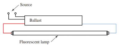
Figure 3. The fluorescent lamp ballast is another form of transformer. The ballast not only provides a high starting voltage to the lamp but also limits the current.
- You May Also Read: Three-Phase Transformer: Working, Selection & Connections
Coupling Transformer
The stages in an amplifier circuit are sometimes coupled together using transformers, Figure 4. The transformers are small in size and are not used to raise or lower voltage, but rather as a way of separating sections or stages of an amplifier system.
The coupling transformer isolates each section of the amplifier circuit so that the design of each section and their individual resistance characteristics do not interfere with the other section. This process is referred to as impedance matching. The transformer is one way to ensure that each section will be compatible with the next.
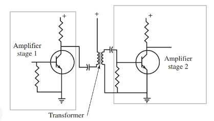
Figure 4. Transformers can be used to match impedance between different stages of electronic circuits.
Isolation Transformers
Isolation transformers are commonly used to separate commercial power systems from computer or other sensitive equipment power supply systems. Typically, they are in a one-to-one ratio, and they neither increase nor decrease voltage.
By using an isolation transformer, the power supply is isolated from the rest of the electrical system. This isolation will prevent or suppress unwanted transient voltages. Transient voltages are voltage spikes that are higher than the typical supply voltage. Examine Figure 5.
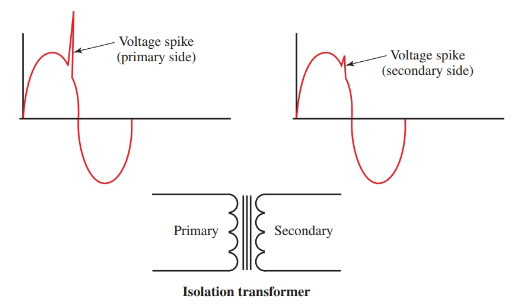
Figure 5. The isolation transformer has a one-to-one turn ratio between the primary and secondary. This type of trans- former is used to provide an isolated power supply to computers or other sensitive equipment.
Transient voltage spikes are compared to typical sine waves. As you can see, the transient spike has a much higher voltage peak than the normal sine wave pattern. The high voltage peak can damage sensitive electronic equipment by exceeding its voltage rating, even if only for a brief period of time.
Transient voltages are caused by switching inductive circuits—such as lighting ballasts, motors, welders, or even the power company transformers—on and off. The isolation transformer suppresses the spikes in the voltage.
Automobile Ignition Coil
The high voltage spark in an automobile electrical system is produced by the ignition coil. The ignition coil is a form of autotransformer. It uses a high turns ratio to develop 30,000 volts or more across the spark plug gap.
You may be wondering how the transformer principle is applied to a DC circuit. A car uses a 12-volt DC power supply, the battery. Look at Figure 6 as we trace the ignition circuit.
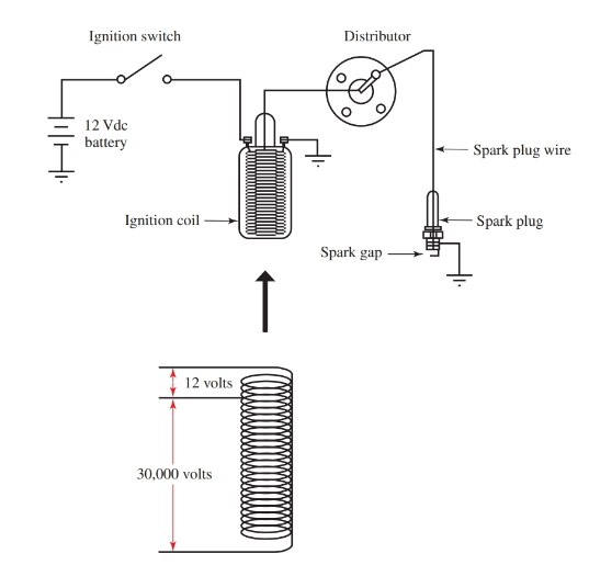
Figure 6. The ignition coil is a form of autotransformer.
- The 12-volt battery is connected in series with an ignition switch. The circuit connects to the ignition coil and then on to the distributor.
- The distributor turns, producing the opening and closing of the circuit. This action produces pulses of electrical energy flow to the coil circuit, turning the coil on and off.
- The pulses produce a rising and falling magnetic field across the winding in the coil, and thus, produced transformer action.
The 12 volts on the primary side of the autotransformer produces over 30,000 volts on the secondary side of the autotransformer.
- The electrical energy flows through the spark plug wire to the spark plug.
- At the spark plug, the circuit has an intentional open. The open in the circuit is at the spark plug gap.
- The 30,000 volts easily arc across the open gap, completing the circuit to chassis ground.
- The arc across the spark plug gap ignites the gasoline vapor, causing an explosion.
- The explosion forces the piston to move, and thus, the engine runs.
Transformer Applications Key Takeaways
These specialized transformer applications play a crucial role in various electrical and electronic systems. Autotransformers provide cost-effective voltage regulation, while circuit breakers enhance electrical safety by preventing overloads and fires. Lighting ballasts optimize the performance of discharge lamps, and coupling transformers enable impedance matching in amplifier circuits. Isolation transformers protect sensitive equipment from power fluctuations, and automobile ignition coils generate the high voltage necessary for engine operation. Each of these applications highlights the importance of transformers in modern technology, demonstrating their essential contribution to reliable power management and system performance.