The article explains the key specifications found on electric motor nameplate details, covering topics like horsepower, voltage, current, speed, efficiency, and enclosure types, as outlined by NEMA standards. It also discusses additional details such as duty cycle, service factor, insulation class, and motor design codes, noting that nameplate information may vary by manufacturer.
The nameplate on an individual electric motor tells the story of what the motor is capable of and its electrical supply requirements.
The National Electrical Manufacturers Association (NEMA) specifies the following data is to be listed on the individual motor nameplates:
- Duty Cycle or Time Rating
- Efficiency
- Frame size
- Frequency
- Full-Load Current (FLC — Full-Load Amps: FLA)
- Full-Load Speed
- Horsepower
- Locked Rotor Indicating Code Letter
- Manufacturer’s Name
- NEMA Design Code
- Number of Phases (for AC Motors)
- Rated Voltage
- Service Factor
- Temperature Rise or Insulation System Class
Because NEMA is an association and not a government agency, it should be noted that not all electric motor manufacturers comply with the NEMA specifications are listed here. The individual motor nameplates may or may not contain all the information specified by NEMA. In some instances, information not specified by NEMA will also be listed on a nameplate.
Since the intent of the electric motor nameplate is to list information concerning the specific motor, the information presented in this section may or may not be found on all motor nameplates. Each item on the nameplate shown in Figure 1 will be discussed.
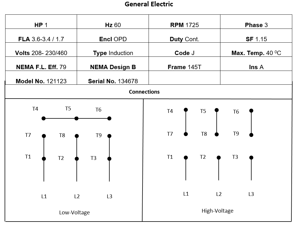
Figure 1. Electric motor nameplate information
1 Horsepower Rating
Electric motors have a rated horsepower (HP) that is determined by the amount of torque they can produce at their running or baseline speed. The nameplate shown in Figure 1 indicates this motor is rated at 1 horsepower.
The term “horsepower” comes from the rating of steam engines. Many years ago, James Watt invented the steam engine. At the time horses and mules were the means of travel and work. To sell his engines, Watt decided to compare the amount of power his steam engine could produce to the working ability of a horse. After various degrees of experimentation, he determined that the average workhorse could do work at the rate of 550 foot-pounds per second (550 ft-lb/s) or 33,000 foot-pounds per minute (33,000 ft-lb/min). In formula;
1 HP = 33,000 ft-lb/min
James Watt also determined that the work of one horsepower would consume 746 watts of electrical power. In formula;
1 HP = 746 watts
2 Hertz
The frequency of the sine waveform of the applied AC source is measured in hertz (Hz — cycles per second). Due to the parallel grid of the utility electrical power generation, transmission, and distribution, the standard frequency used throughout the United States and Canada is 60 Hz. The standard frequency of the parallel utility electrical-power grid in Europe is 50 Hz.
The RPM of the electric motor depends on the applied frequency of the AC source and the number of magnetic poles per phase installed in the motor at the point of manufacture. Rated in “pole pairs”, the synchronous speed of the electromagnetic field rotating about the inner face of a 2-pole motor operating at 60 Hz is 3600 RPMs:
60 cycles/second x 60 seconds/minute = 3600 cycles (rpms) /minute
The synchronous speed of the electromagnetic field rotating about the inner face of a 2-pole electric motor operating at 50 Hz (calculated in the same manner, but replacing the “60 cycles/second” with “50 cycles/second”) is only 3000 RPMs.
The synchronous speed of the electromagnetic field rotating about the inner face of a 4-pole electric motor operating at 60 Hz is 1800 RPMs. The synchronous speed of the electromagnetic field rotating about the inner face of a 4-pole motor operating at 50 Hz is only 1500 RPMs.
The nameplate shown in Figure 1 indicates the motor is rated for operation at 60 Hz. Some manufacturers design electric motors — the AC induction motors — for sale/use in both the United States and Europe. Electric motors with a frequency rating of 50/60 Hz shown on the nameplate are not uncommon.
3 Revolutions per Minute
Revolutions per Minute, or RPMs, (also referred to as “baseline speed”), indicate(s) the speed at which the electric motor will operate at rated load. Rated load occurs when the horsepower requirements of the driven load equate to the horsepower rating of the motor and the electric motor is supplied its rated voltage, as listed on the nameplate, at the rated frequency, as also listed on the nameplate. As shown in Figure 1, this particular electric motor driving a 1 HP connected load will turn at 1725 RPMs, if supplied 208 VAC, 230 VAC, or 460 VAC at 60 Hz. The wiring connections listed at the bottom of the nameplate have to be honored according to either the “low-voltage” configuration (208 or 230 VAC) or the “high-voltage” configuration (460 VAC).
Since this is an AC induction motor and there is no external power supply to the rotor circuit, the rotor cannot turn at the synchronous speed of the electromagnetic field rotating about the inner face of the stator assembly. The difference between the synchronous speed of 1800 RPMs (discussed in the previous section — this must be a 4-pole induction motor) and the rated 1725 RPM is the amount of slip between the two electromagnetic fields. The movement of the stator circuit rotating electromagnetic field — due to the slip — cutting across the rotor windings induces a voltage upon the rotor windings. The induced voltage causes current to flow in the shorted rotor windings. The counter-electromagnetic field produced by the current flow in the rotor winding is what produces the torque or “motor action” of the AC induction motor.
Besides the synchronous speed, the actual speed of the turning rotor depends on the torque requirement of the connected load. Operated at no load, the actual speed of the turning rotor will be close to the synchronous speed of the stator circuit’s rotating electromagnetic field. The stator winding current will be of low or minimum value; the slip will be near zero, and the delivered torque will be near zero.
As the torque requirements of the connected load increase — moving from no load toward full-load — the actual speed of the rotor begins to slow; the stator winding current; the amount of slip; and the delivered torque all begin to increase.
When the torque requirements of the connected load reaches 1 horsepower, and the motor is supplied its rated voltage (208, 230 or 460 VAC, according to the AC supply voltage rating and the correct wiring connections) at 60 Hz, the actual speed of the turning rotor will drop to 1725 revolutions per minute (the nameplate listed RPM). The stator circuit will draw the full-load current indicated on the nameplate (FLA) according to the voltage rating.
If the torque requirements of the connected load increase beyond 1 horsepower and the motor is supplied either 208 volts, 230 volts, or 460 volts at 60 Hz: the actual speed of the turning rotor will slow down below the nameplate-rated RPM; the stator winding current will increase beyond nameplate FLA rating; the amount or percent of the slip will increase, and the delivered torque will increase in response to the mechanical overload. This process will continue until the %-slip of the slowed rotor reaches about 20%, at which time the AC induction motor will enter breakdown torque and abruptly stop in a locked-rotor condition.
Full-load motor speed is determined by several factors, the main factor being the synchronous speed. Another factor is the design of the motor itself. The type of squirrel-cage winding (configuration of the rotor bars that make up the squirrel cage) in the rotor greatly affects the running and full-load speed of a given AC induction motor.
4 Number of Phases
The term phase indicates the number of phases required in the electrical supply that the AC induction motor is designed to operate. The 3 beside Phase on the nameplate in Figure 1 indicates that this is a 3-phase AC motor —the motor operates on 3-phase AC power. Most industrial AC induction motors are rated 3-phase, which means that the AC power supply is three separate yet interconnected single-phase AC lines with the voltages across the respective windings 120° out of phase with each other. Other alternating current motors maybe rated as either single-phase or 2-phase. Although there are some single-phase AC induction motors used in industrial applications, the more predominant use is in residential applications. And, although 2-phase AC induction motors do exist, their use is extremely rare in industry operating in the United States.
5 Full-Load Amps
The full-load amps (FLA), full-load current (FLC), or rated-load current (RLC) of an AC induction motor (all three terms refer basically to the same thing) is the current drawn by the electric motor when it is operated at the rated load, rated voltage, and rated frequency (AC motors) as found on the motor nameplate. As discussed in Section 3 with the RPM of the motor, the AC induction motor will draw less than full-load current if operated either with no load or with a load rated less than the horsepower rating. The motor will draw more current than listed as full-load on the nameplate if operated in a mechanical overload condition.
The nameplate shown in Figure 1 indicates the motor is rated for three separate voltages; therefore there are three different/separate full-load currents listed: One for each voltage rating. If the motor leads are configured (connected) to operate at 208 VAC, the AC induction motor should draw 3.6 amperes when operating at full load. If connected to operate at 230 VAC, the ac induction motor should draw 3.4 amperes when operating at full load. If connected to operate at 460 VAC, the AC induction motor should draw 1.7 amperes when operating at full load. Instead of FLA, FLC, or RLC, some motor nameplates simply list the full-load current as “AMPS”.
6 Enclosures
Depending on the application, electric motors will have different types of enclosures. Some of the common enclosures include:
Explosion-proof (EXP) — these enclosures are designed for areas that have hazardous atmospheres; the end bells and the cylindrical motor housing are totally enclosed and non-vented.
Open Drip Proof (ODP) — these enclosures are probably the most common used. The end bells of the cylindrical motor housing have openings to permit ventilation through the motor windings. The nameplate shown in Figure 1 indicates the motor enclosure is rated ODP.
Totally Enclosed Fan Cooled (TEFC) — these enclosures are also in common use. The end bells and the cylindrical motor housing are sealed to prevent the entrance of moisture or dirt. Often the outer surface of the cylindrical motor housing is molded with fins to increase the outer surface area of the housing. A fan is normally mounted externally on a jackshaft on the non-drive end of the motor with a protective fan shroud to help cool the motor.
Totally Enclosed Nonvented (TENV) — these enclosures are designed to be frequently hosed down. TENV electric motors are generally used in harsh environments such as chemical or food-processing plants.
7 Duty Cycle
The National Electrical Code defines “duty cycle “of an electric motor as any one of five different classifications: either continuous, intermittent, periodic, short-time or varying duty. When an AC induction motor is classified as;
Continuous Duty — the motor operates at a substantially constant load for an indefinitely long time. The nameplate shown in Figure 1 indicates this electric motor has a continuous duty cycle.
Intermittent Duty — the motor operates for alternate intervals of (1) load and no load; or (2) load and rest; or (3) load, no load, and rest.
Periodic Duty — the motor operates intermittently and the load conditions are regularly recurrent.
Short-Time Duty — the motor operates at a substantially constant load for a short and definite, specified time.
Varying Duty — the motor operates at loads, and for intervals of time, both of which may be subject to wide variation.
The duty cycle indicates the amount of time the motor is expected to operate. NEC stipulates “any motor application shall be considered to be for continuous duty unless the nature of the apparatus it drives is such that the motor cannot operate continuously with the load under any condition of use.”
8 Service Factor
The service factor (SF) specified on the motor nameplate gives the allowable horsepower overloading of the electric motor which may be carried out under the conditions specified for the service factor at rated voltage and rated frequency.
The allowable overloading is determined by multiplying the horsepower rating on the nameplate by the service factor. The nameplate shown in Figure 1 indicates the electric motor is rated 1 HP. With a service factor of 1.15, the motor can be overloaded up to 1.15 horsepower. If the motor is operated in the service factor range continuously, it will cause a reduction in motor speed and efficiency, and an increase in the motor’s operating temperature. According to the rated service-factor, the increase in motor operating temperature will not cause undue deterioration of the insulation.
Selecting an electric motor with a service factor greater than 1 allows for cooler winding temperatures when the motor is operated either at rated load or at less than rated load; it protects the motor against intermittent heat rises; it helps to offset the excess heat produced by the variance in the single-phase AC winding currents due to low or unbalanced line voltages.
The manufacturer establishes Service factors for motor operations at rated voltage, frequency, and ambient temperature at sea level conditions. If the horsepower requirements of the intended connected load fall between standard size horsepower ratings, it is generally better to install an electric motor of the next higher horsepower rating and operate it under load, rather than depend on operating the motor in the service factor range to attain the required horsepower rating.
9 Voltage Rating
The nameplate shown in Figure 1 indicates this is a dual-voltage AC induction motor. Whether the electric motor will operate satisfactorily at low voltage or high voltage depends on the motor field-terminal winding connections. If the motor is connected for low-voltage operation, as indicated by the terminal connections in the wiring diagram to the left on the nameplate, it will operate satisfactorily on either 208 or 230 VAC. If the motor is connected to the high-voltage operation, as indicated by the terminal connections in the wiring diagram to the right on the nameplate, it will operate satisfactorily on 460 VAC.
10 Type of Motor
Three-phase AC motors can be divided into three general types: squirrel-cage, wound-rotor, and synchronous. Both the squirrel-cage rotor motors and the wound-rotor motors are induction motors. As discussed in Section 3, Revolutions per Minute, the rotor circuit in an induction motor does not have an external power supply: Voltage is induced in the rotor windings by the revolving electromagnetic field in the stator assembly when power is applied to the stator windings.
Most AC motors listed as induction will be the squirrel-cage type, which describes the type of rotor used in the electric motor — the rotor bars molded in a cast of aluminum have the appearance of a squirrel cage or the paddle wheel on a steamboat (Figure 2).
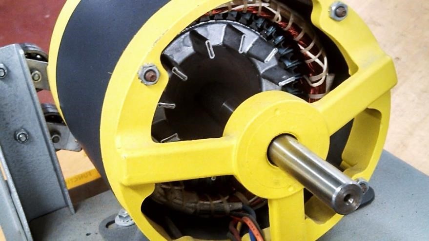
Figure 2. In a squirrel-cage rotor AC induction motor, the rotor bars molded in a cast of aluminum have the appearance of a squirrel cage or the paddle wheel on a steamboat
Wound-rotor induction motors (Figure 3) are easily recognized by the three slip rings on the rotor shaft. Instead of casting as used in squirrel-cage rotors, the wound-rotor has a steel frame on which windings of insulated wire are installed. Interconnected in a wye configuration on one common end, the other ends of the three single-phase windings are connected one each to the three slip rings.

Figure 3. Wound-rotor AC induction motors are easily recognized by the three slip rings on the rotor shaft
Through brushes riding on the slip rings, a 3-phase or “3-leg” wye-connected resistive load bank can control the magnitude of the rotor current. Controlling the magnitude of the rotor current with the amount of resistance in series with the respective single-phase rotor windings allows some speed control of the wound-rotor motor, although the 3-phase resistive load bank is normally used to lower the impact of the starting torque of the induction motor — the individual resistors in the load bank are bypassed or shorted in three or four successive steps until all the resistance is removed from the rotor circuit.
Synchronous motors are easily recognized by the two slip rings on the rotor shaft. Although started as an induction motor with the use of an amortisseur winding on the rotor assembly, synchronous motors are not induction-type AC motors.
In addition to the amortisseur winding, the rotor assembly of an AC synchronous motor consists of an electromagnet. Once started, DC power is applied to the winding of the electromagnet through the two slip rings. The magnetic poles of the rotor’s electromagnet locks in or with the opposite poles of the stator assembly’s rotating magnetic field: The rotor assembly now turns at synchronous speed — at zero slip.
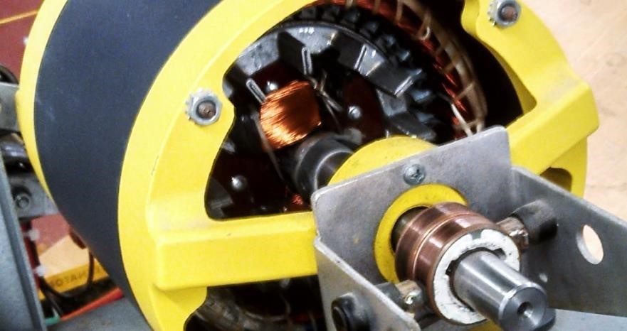
Figure 4. AC Synchronous motors are easily recognized by the two slip rings on the rotor shaft
11 Code Letter
The locked-rotor code letter, which can be listed as either A, B, C, D, E, F, G, H, J, K, L, M, N, P, R, S, T, U, or V on the AC induction motor nameplate, is determined by the construction of the squirrel-cage rotor. The locked-rotor code letter can be used with the kVA values listed in National Electric Code to determine the approximate amount of inrush current that will be drawn from the power supply when the motor is started under load. The nameplate shown in Figure 1 indicates that this particular AC induction motor was constructed with a type J rotor. NEC indicates that the kilovolt-amperes per horsepower at locked rotor for a type J rotor range from 7.1 to 7.99 kVA per HP. For one horsepower and assuming the motor will operate on 208 volts, the 3-phase AC power formula, solved for current, can be used to determine the inrush current range of this motor.
Low-Side Locked-Rotor Amps: [1000 (/k) x 7.1 kVA/HP x 1 HP] ÷ (1.732 x 208 volts) = 19.7 amps
High-Side Locked-Rotor Amps: [1000 (/k) x 7.99 kVA/HP x 1 HP] ÷ (1.732 x 208 volts) = 22.2 amps
The AC induction motor referred to in this electric-motor nameplate should have a starting current between 19.7 amps and 22.2 amps.
12 Maximum Temperature
Maximum temperature specified on the motor nameplate indicates the maximum amount of rising in ambient temperature the electric motor will exhibit when operated continuously at the full load condition. The nameplate shown in Figure 1 indicates a maximum temperature rise of 400C for this motor.
13 Motor Efficiency
The NEMA full-load efficiency indicates the overall efficiency of the AC induction motor. The nameplate shown in Figure 1 indicates this motor has an efficiency of 79%. The NEMA full-load efficiency basically lists as a percentage the amount of electrical energy supplied to the electric motor that is converted into kinetic energy. The remaining power is a loss that is converted mostly into heat.
14 NEMA Design Letters
Induction motors have different operating characteristics determined by their design. Such factors as the amount of iron used in the stator assembly, the wire size and the number of turns of wire in the stator windings, and the rotor design (the type of squirrel-cage rotor) all play a part in establishing the operating characteristics of the ac induction motor.
To establish some uniformity in the operating characteristics of ac induction motors, not too many years ago NEMA assigned code letters to general purpose motors based on factors such as starting current, % of slip, breakdown torque, and locked rotor torque. The NEMA code letters are A, B, C, and D.
Design A AC induction motors with the design code letter A exhibit normal starting torque, but with high starting current. Design A motors are designed for brief heavy overloads.
Design B AC induction motors with the design code letter B are the most common. These motors exhibit normal starting torque with the low starting current. Design B motors have sufficient lock rotor starting torque to start most industrial loads. The nameplate shown in Figure 1 lists this motor as a NEMA Design B motor.
Design C AC induction motors with the design code letter C exhibit high starting torques with low starting currents. Used to start heavy loads, Design C motors exhibit a large amount of rotor slip when the load is added.
Design D Like Design C motors, AC induction motors with the design code letter D exhibit high starting torques with low starting currents. Design D motors also exhibit a large amount of rotor slip when the load is added.
The NEMA Design code should not be confused with the locked rotor indicating code letter (Section 11, Code Letter) listed on many electric-motor nameplates.
15 Frame Sizes
The frame number on the nameplate indicates the type and size of the motor frame. The nameplate shown in Figure 1 indicates this electric motor has 145T frame.
A manufacturer’s chart is generally required to determine the exact dimensions of the electric motor frame. The manufacturer’s chart normally lists the shaft height above the bottom of the base; the distance from the center hole on the front of the motor base mount to the center of the shaft; the distance from the bottom of the motor to the top; and the width of the motor excluding the terminal connection box.
A general rule of thumb when dealing with frame sizes is that the centerline shaft height above the bottom of the base in inches is equal to the first two digits of the frame number divided by 4. A frame 145T frame, listed in Figure 1, would have a shaft height of 3.5 inches (14 divided by 4) above the mounting base of the motor.
In addition to frame numbers, letters also appear at the end of the numbers to represent different frame styles. The letters include C, D, H, J, JM, JP, S, T, U, Y, and Z:
C The suffix letter C designates a flange-mounted electric motor. The C frame is the most popular style for flange-mounted motors. It has a specific threaded bolt-hole pattern on the shaft end of the motor housing (face of the motor) that permits direct mounting to the driven device.
D The suffix letter D also designates a flange-mounted electric motor. The flange diameter of D frame motors is larger than the body of the motor. The bolt-holes are not threaded; instead, they are designed for bolts to pass through the holes.
H Used on some 55 frame electric motors, the suffix letter H indicates that the base of these frames can be mounted in either 56, 743T, or 745T mounting positions.
J The suffix letter J indicates that the electric motor is specially designed to mount to jet pumps. A J frame motor has a threaded stainless steel shaft and a standard 56C face.
JM The suffix letters JM indicate that the jet pump shaft is designed for a mechanical seal. A JM frame electric motor also has a 56C face.
JP The suffix letters JP indicate that the jet pump shaft is designed for a packing type mechanical seal.
S The suffix letter S indicates that the electric motor has a short shaft and is to be directly coupled to a driven load. These electric motors are not intended for with belt drives.
T NEMA standardized The T frame motors after 1964. Any electric motor with the letter T at end of the numerical frame size was manufactured after 1964.
U The first time NEMA standardized motor frames were introduced in 1952. Any electric motor with the letter U at the end of the numerical frame size was manufactured between 1952 and 1964.
Y The suffix letter Y on the frame number indicates that the electric motor has a special mounting configuration. The suffix letter Y does not indicate what the special mounting configuration is, only that it is nonstandard.
Z The suffix letter Z indicates that the electric motor has a special shaft. The shaft could be longer or larger in diameter than a standard shaft. It could be threaded or contain holes. Z in the frame number of the motor only indicates that the shaft is special in some undefined way.
16 Insulation Temperature Rating
The classification of insulation, which reflects the operating temperature rating of the winding insulation, greatly affects the lifespan of an electric motor. Motor operating temperature is based on the hottest point along the inner surfaces of the motor assembly/enclosure when the motor is operated under full-load conditions. Motor operating temperature is determined by the temperature rise of the motor and by the surrounding ambient air temperature. Electric motors that operate in hotter climates, like near the equator, should have a higher insulation temperature rating as compared to electric motors, which operate near the United States and Canadian border.
The thermal capacity of different insulations is rated as Class A, Class B, Class F, or Class H. These specific letters indicate the maximum degree of temperature each type of insulation is designed to handle over a 20,000-hour period with the electric motor operating at full load. The nameplate shown in Figure 1 indicates this motor has an insulation temperature rating of Class A.
At 1050C, Class A insulations have the lowest operating-temperature rating of the four classes. Class H insulations have the highest operating-temperature rating at 1800C. In-between these two extremes, Class B insulations have an operating temperature rating of 1300C, whereas, Class F insulations have an operating temperature rating of 1550C.
17 Model Number
Normally used to purchase a replacement motor with identical ratings and operating characteristics, the model number of an AC induction motor, or any other electric motor for that matter, is assigned by the manufacturer. The nameplate shown in Figure 1 indicates the model number this motor is 121123.
18 Serial Number
The serial number, also assigned by the manufacturer, is used to identify a particular electric motor. No other electric motor purchased from a given manufacturer should have the same serial number. When registering an electric motor for the manufacturer’s warranty, listing the model number identifies the type of motor placed under warranty, whereas the serial number segregates this particular motor from any other electric motor in the plant or another manufacturing facility. The nameplate shown in Figure 1 indicates the serial number this motor is 134678.
Electric Motor Nameplate Key Takeaways
The specifications listed on an electric motor nameplate are critical for ensuring proper selection, operation, and maintenance in various applications. Key details such as horsepower, voltage, current, speed, and efficiency determine whether a motor can meet the mechanical demands of industrial machinery, HVAC systems, or pumps. Enclosure types (ODP, TEFC, EXP) ensure motors operate safely in different environments—from wet conditions to hazardous atmospheres. Duty cycle and service factor indicate how long and how hard a motor can run, which is essential for applications with intermittent or continuous loads. Additionally, insulation class and temperature ratings prevent overheating, extending motor life in high-temperature settings.