When a source of DC power is needed, a DC power supply is used. A DC power supply is a device that converts alternating current (AC) to regulated direct current (DC) for use in electrical circuits. A DC power supply consists of a rectifier, filter, voltage regulator, and voltage divider. See Figure 1.

Figure 1. A block diagram shows the basic components of a DC power supply.
A DC power supply may also include a transformer and a voltage multiplier. A transformer is an electric device that uses electromagnetism to change the voltage from one level to another or to isolate one voltage from another.
Depending on the cost and application, a DC power supply may contain all or some of these components.
A rectifier is an electrical circuit that changes AC into DC. Rectifiers typically consist of one or more diodes used to control the flow of current in a circuit.
Three basic types of rectifiers used in single-phase DC power supplies are half-wave, full-wave, and full-wave bridge rectifiers.
Half-Wave Rectifier Working
A half-wave rectifier is an electrical circuit containing an AC source, a load resistor (RL), and a diode that permits only the positive half cycles of the AC sine wave to pass, which creates pulsating DC. See Figure 2.
Half-wave rectification is accomplished because the current is allowed to flow only when the anode terminal of diode D1 is positive with respect to the cathode. Electrons are not allowed to flow through the rectifier when the cathode is positive with respect to the anode.
Half-Wave Rectifier Output Voltage
The output voltage of the half-wave rectifier is considered pulsating DC when half of the AC sine wave is cut off.
Pulsating DC is direct current that varies in amplitude but does not change polarity.
The rectifier can pass either the positive or negative half of the input AC cycle depending on the polarity of the diode in the circuit. Half-wave rectifiers are considered inefficient for many applications because one-half of the input cycle is not used.
TECH FACT
DC power supplies, such as those used for phone and tool chargers, are classified as regulated or unregulated.
It is important to know the difference when replacing, testing, or troubleshooting a rectifier. For example, a 12 VDC/500 mA regulated rated rectifier should measure about 12 VDC for any load between 0 to 500 mA.
A 12 VDC/500 mA unregulated rated rectifier will measure a much higher voltage, up to about 16 VDC, for loads less than 500 mA and about 12 VDC only when the load reaches 500 mA.
Both types will decrease the voltage output when overloaded above their ratings.
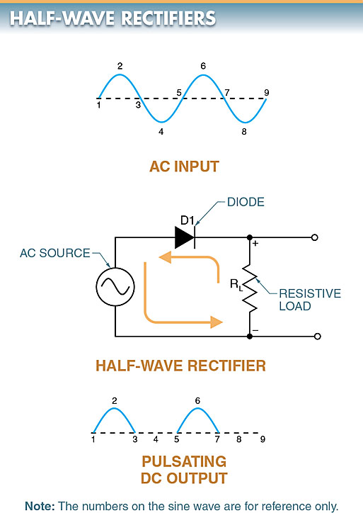
Figure 2. A half-wave rectifier circuit diagram
Full-Wave Rectifier Working
A full-wave rectifier is an electrical circuit containing two diodes and a center-tapped transformer used to produce pulsating DC. See Figure 3.
The center-tapped transformer supplies out-of-phase voltages to the two diodes. When a voltage is induced in the secondary from point A to B, point A is positive with respect to point N. Current flows from N to A, through the load RL, and through diode D1. Diode D1 is forward-biased and allows electrons to flow. Diode D2 is reverse-biased and blocks current flow because point B is negative (–) and point A is positive (+).
When the voltage across the secondary reverses during the negative half cycle of the AC sine wave, point B is positive with respect to point N. Current then flows from N to B, through the load, and through diode D2. Diode D2 is forward-biased and allows electrons to flow. Diode D1 is reverse-biased and blocks current because B is positive with respect to N. This is repeated every cycle of the AC sine wave, producing a full-wave DC output.
Full-Wave Rectifier Output Voltage
The output voltage of a full-wave rectifier has no off-cycle. Electrons flow through the load during both half cycles. The constant electron flow results in a complete output signal. A full-wave rectifier is more efficient and has a smoother output than a half-wave rectifier.
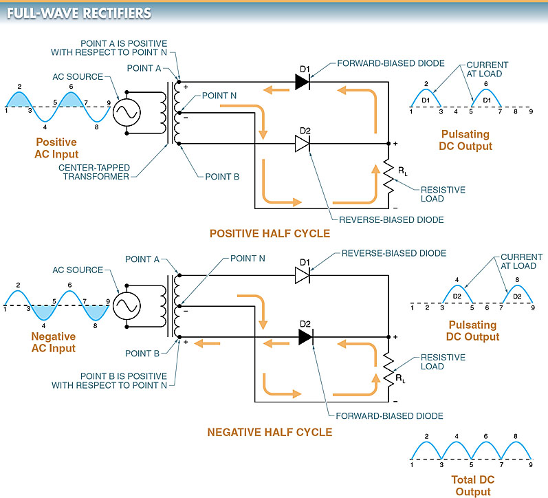
Figure 3. A full-wave rectifier circuit diagram.
Full-Wave Bridge Rectifier Working
A full-wave bridge rectifier is an electrical circuit containing four diodes that allow both halves of a sine wave to be changed into pulsating DC.
A full-wave bridge rectifier does not require a center-tapped transformer. It uses lower voltage diodes than the center-tapped circuit of a full-wave rectifier.
The bridge diodes only need to block half as much reverse voltage as a center-tapped transformer diode for the same output voltage. See Figure 4.
When the voltage is positive at point A and negative at point B, electrons flow from point B through diode D2, load RL, and diode D1 to point A. When the AC supply voltage is negative at point A and positive at point B, electrons flow from point A through diode D4, load RL, and diode D3 to point B.
Full-Wave Bridge Rectifier Output Voltage
One disadvantage of a full-wave bridge rectifier is that on each alternation, the DC in the circuit must flow through two series-connected diodes. The forward DC voltage drop across the two rectifiers is, therefore, greater than the drop across a single rectifying diode. However, the voltage drop across silicon diodes is small (0.6 V), and the loss typically can be tolerated.
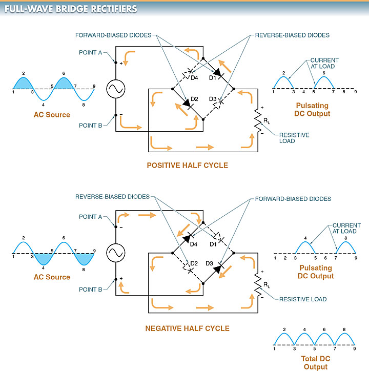
Figure 4. A full-wave bridge rectifier circuit diagram.
Rectifier Voltage Measurements
Measuring voltages in a rectifier requires knowledge of some of the terminology, math, and instruments necessary to take accurate measurements.
A rectifier uses both AC and DC. Care must be exercised when measuring AC and DC and when converting or comparing any AC value to a DC value. Measurements in a rectifier are typically taken with either a DMM or an oscilloscope. An oscilloscope can show the waveforms in addition to the voltage value. See Figure 5.
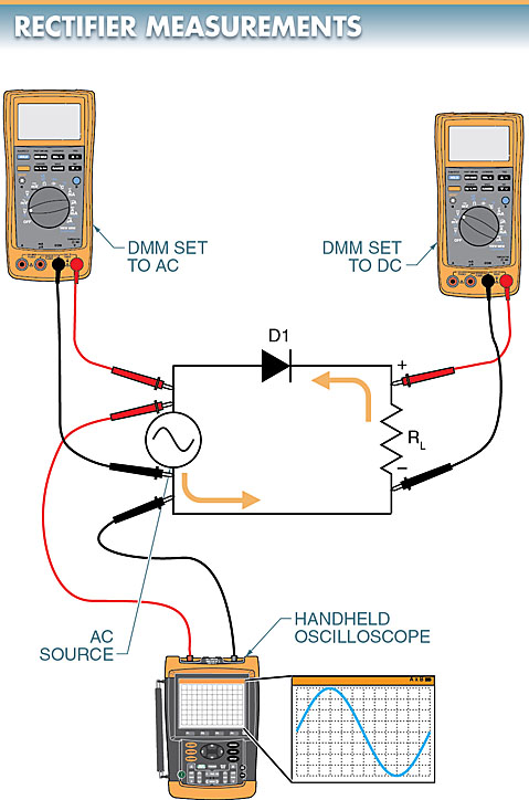
Figure 5. Either a DMM or an oscilloscope can be used to take measurements in a rectifier circuit.
