You will learn about basic magnetism and electromagnetism. Three important electromagnetic devices are introduced: the relay, the generator, and the motor. All of these devices are important in renewable energy systems. Relays are commonly used in many applications to switch current on and off. Generators and motors are rotating electromagnetic machines that generate electrical power (in the case of the generator) and use electrical power to produce mechanical motion (in the case of the motor). Generators are used in wind and hydroelectric systems, and motors are used in solar tracking systems.
The Magnetic Field
A permanent magnet, such as the bar magnet shown in Figure 1, has a magnetic field surrounding it. All magnetic fields have their origin in moving charge, which in solid materials is caused by moving electrons. In certain materials, such as iron, atoms can be aligned so that the electron motion is reinforced, creating an observable field that extends in three dimensions.
To explain and illustrate magnetic fields, Michael Faraday drew lines of force, or flux lines, to represent the unseen field. Flux lines are widely used as a description of a magnetic field, showing the strength and direction of the field. The flux lines never cross. When lines are close together, the field is more intense; when they are farther apart, the field is weaker. The flux lines always extend from the North Pole (N) to the South Pole (S) of a magnet. Although the number of lines for any given magnet can be extremely large, only a few representative lines are usually shown in drawings.
When unlike poles of two permanent magnets are placed close together, their magnetic fields produce an attractive force, as indicated in Figure 2(a). When two like poles are brought close together, they repel each other, as shown in Figure 2(b).
Magnetic Flux
The group of force lines going from the north pole to the south pole of a magnet is called the magnetic flux and is symbolized by φ Several factors determine the strength of a magnet, including the material and physical geometry as well as the distance from the magnet. Magnetic flux lines tend to be more concentrated at the poles.
The mks unit of magnetic flux is the weber (Wb), which is a very large unit. In most practical situations, the microweber (μW), which is equal to 100 flux lines, is more appropriate. The magnetic flux density (B) is the amount of flux, φ per unit area (A) perpendicular to the magnetic field. Flux density is defined mathematically as follows;
\[B=\phi /A\]
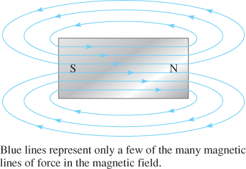
Figure 1: Magnetic Lines of Force around a Bar Magnet
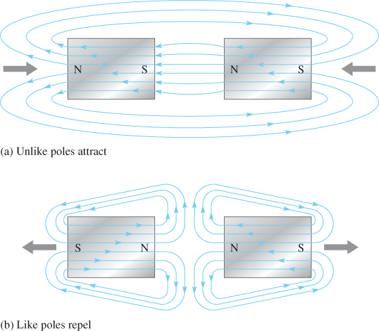
Figure 2: Magnetic Attraction and Repulsion
The flux density is in Wb/m2 when the magnetic flux is in Weber and the area is in square meters. One Wb/m2 defines the Tesla (T), which is the mks unit. The Tesla represents a large unit; the strongest permanent magnets are above 5 T. The Gauss (G) is the much smaller cgs unit for flux density (104G = 1T). The meter used to measure flux density is named the gauss meter (rather than the teslameter).
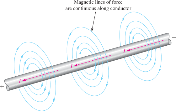
Figure 3: Magnetic Field around a Current-Carrying Conductor. The red arrows show the direction of electron current.
Electromagnetism
Current produces a magnetic field around a conductor, as illustrated in Figure 3. The invisible lines of force of the magnetic field form a concentric circular pattern around the conductor and are continuous along its length. Although the magnetic field cannot be seen, it is capable of producing visible effects. For example, if a current-carrying wire is inserted through a sheet of paper in a perpendicular direction, iron filings placed on the surface of the paper arrange themselves along the magnetic lines of force in concentric rings, as illustrated in Figure 4(a). Figure 4(b) shows that the needle of a compass placed in the magnetic field points in the direction of the lines of force.
Electromagnet
Figure 5(a) illustrates a basic magnetic circuit with a coil of wire around a magnetic material. The current through the coil creates a magnetic field represented by flux lines along the magnetic path. An electromagnet works on the same principle except that an air gap exists in the magnetic material so that the magnetic field set up by the current in the coil of the wire extends from the North Pole to the South Pole. When the current through the coil reverses direction, the magnetic field also reverses direction, as shown in Figure 5(b). An electromagnet can have various configurations, but a U-shape magnetic core is shown.
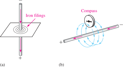
Figure 4: Visible Effects of a Magnetic Field
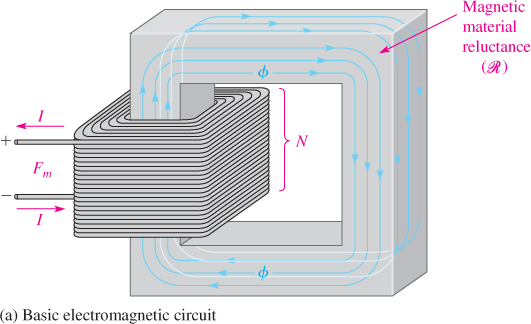
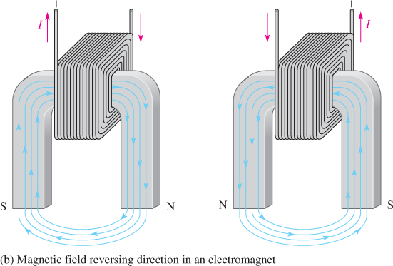
Figure 5: Basic Electromagnetic Circuit and Electromagnet
Relay
Figure 6 shows the basic operation of an armature-type relay with a normally open (NO) contact and one normally closed (NC) contact. When there is no current through the coil, the armature is held against the upper contact by the spring, thus providing continuity from terminal 1 to terminal 2, as shown in Figure 6(a). When energized with coil current, the armature is pulled down by the attractive force of the magnetic field and makes a connection with the lower contact to provide continuity from terminal 1 to terminal 3, as shown in Figure 6(b). A typical armature relay and its schematic symbol are shown in Figure 7.
Another widely used type of relay is the reed relay. Like the armature relay, the reed relay uses an electromagnetic coil. The contacts are thin reeds of magnetic material and are usually located inside the coil. Reed relays are faster, are more reliable, and produce less contact arcing than armature relays. However, they have a less current-handling capability and are more susceptible to mechanical shock.
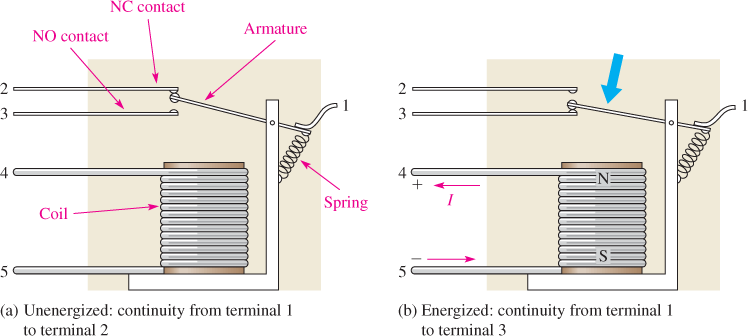
Figure 6: Basic Structure of a Single-Pole, Double-Throw Armature Relay
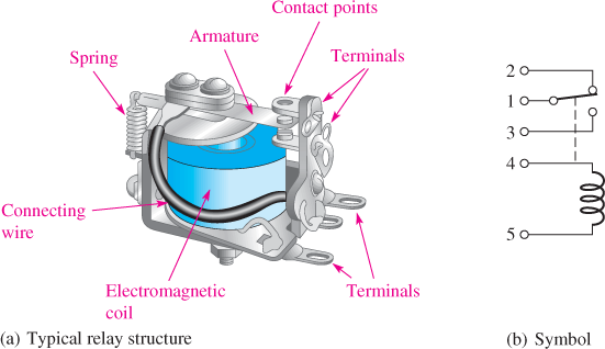
Figure 7: Typical Armature Relay
AC Generators
The AC generator is an electromagnetic machine that produces a sinusoidal voltage. The basic principle of an ac generator can be understood using a simplified single-loop model, as shown in Figure 8. The loop is mechanically driven by a rotating force from a motor shaft, wind turbine blades, or water-driven turbine blades. As the loop rotates through the magnetic field, a voltage is induced across the slip rings. When a load is connected via the brushes, a current is produced and power is delivered to the load.
Each revolution of the loop produces one cycle of a sine wave. The positive and negative peaks occur when the loop cuts through the maximum number of flux lines. The rate at which the loop spins determines the time for one complete cycle and the frequency. If it takes 1/60 of a second to make a revolution between a single set of poles, the period of the sine wave is 1/60 second and its frequency is 60 Hz.
The single-loop generator in Figure 8 produces only a very tiny voltage. Instead of using permanent magnets, a practical generator usually has hundreds of loops that are wound on a magnetic core forming an electromagnet for the rotor. Two basic types of generator are the rotating-armature and the rotating-field. In a motor or generator, the armature is the power producing component.
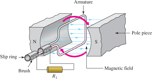
Figure 8: Simplified AC Generator
Rotating-Armature Generator
In a rotating-armature generator that has multiple loops and many pole-pairs, the magnetic field is stationary and is supplied by permanent magnets or electromagnets operated from dc. With electromagnets, field windings are used instead of permanent magnets. These windings provide a fixed magnetic field that interacts with the rotor coils. The output power is taken from the rotor through the slip rings and brushes.
Rotating-Field Generator
Figure 9 shows how a rotating-field generator can produce three-phase sine waves with an electromagnetic rotor. A permanent magnet rotor is shown for simplicity. AC is generated in each set of windings as the North Pole and the south pole of the rotor alternately sweep by a stator winding. The stator winding is separated by 120° causing the sine wave outputs also to have 120° between them. Three-phase (abbreviated 3φ) is generated by power companies, which is then converted to single-phase (1φ) for residential users.
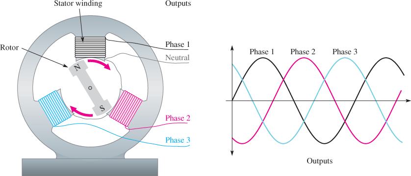
Figure 9: Rotating-Field Generator
Motors
The rotor in dc motors contains the armature winding, which sets up a magnetic field. The rotor moves because of the attractive force between opposite poles and the repulsive force between like poles, as illustrated in the simplified diagram of Figure 10. A force of attraction exists between the south pole of the rotor and the north pole of the stator (and vice versa). As the two poles near each other, the polarity of the rotor current is suddenly switched by the commutator, reversing the magnetic poles of the rotor. The commutator serves as a mechanical switch to reverse the current in the armature just as the unlike poles are near each other, thus continuing the rotation of the rotor. A shaft is connected to the rotor; as the rotor moves, the shaft turns to provide mechanical torque.
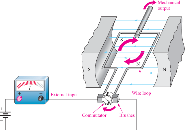
Figure 10: Simplified DC Motor
Some dc motors do not use a commutator to reverse the polarity of the current. Instead of supplying current to a moving rotor, the magnetic field is rotated in the stator windings using an electronic controller.
Magnetism and Electromagnetic Review Questions
- Discuss the repulsive and attractive forces in magnets.
- How is an electromagnetic field produced?
- Describe the difference between a generator and a motor.
- Name two basic types of AC generator.
Answers
- All magnets have two poles: north and south. Like poles repel; unlike poles attract.
- Moving charge (current) in a conductor creates a magnetic field.
- A motor converts electrical energy to mechanical (rotational) energy. A generator does the opposite.
- Rotating armature and rotating field.
Magnetism and Electromagnetic Devices Key Takeaways
Understanding the principles of magnetism and electromagnetism, along with the operation of key devices like relays, generators, and motors, is essential due to their widespread applications in modern technology—particularly in renewable energy systems. Relays play a crucial role in automation by safely switching electrical circuits, while generators and motors are fundamental in converting energy forms. Generators are vital for harnessing natural resources like wind and water to produce electricity, and motors enable motion in systems such as solar trackers that optimize energy capture. These devices not only illustrate the practical use of electromagnetic concepts but also support the development of efficient, sustainable energy solutions critical to our future.