The article discusses various types of DC power supply filters—capacitive, L-section resistive, L-section inductive, and pi-section filters—used to reduce ripple and smooth out rectified DC voltage. It explains the components, configurations, and operating principles of each filter type to improve DC output quality.
A filter is a circuit in a power supply section that smooths the pulsating DC to make it more consistent. A filter minimizes or removes ripple voltage from a rectified output by opposing changes in voltage and current.
The filtering process is accomplished by connecting parallel capacitors and series resistors or inductors to the output of the rectifier. A capacitor smoothes voltage, while an inductor smoothes current.
Capacitive Filter
A capacitive filter is a circuit consisting of a capacitor and a resistor connected in parallel. The capacitive filter provides a maximum voltage output to a load.
Since a large capacitor is needed, an electrolytic capacitor is typically used. As pulsating DC voltage from a rectifier is applied across capacitor C1, it charges to the peak voltage. See Figure 1.
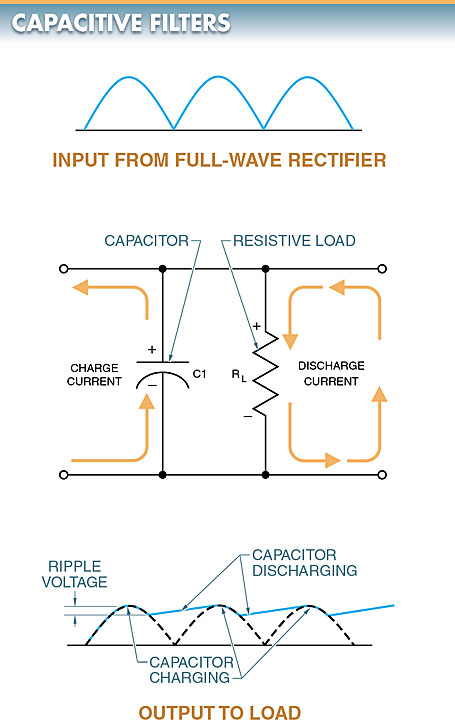
Figure 1. A capacitive filter circuit diagram and output waveform.
Between peaks, the capacitor discharges through the resistive load RL, and the voltage gradually drops.
Ripple voltage is the amount of varying voltage present in a DC power supply.
In a capacitive filter, the ripple voltage is the voltage drop before the capacitor begins to charge again. The amount of discharge between voltage peaks is controlled by the resistor-capacitor (RC) time constant of the capacitor and the load resistance.
If the load resistance is large and the capacitance is large, the ripple voltage will be small, resulting in a smooth output. Ripple voltage increases when the load increases on the capacitive filter.
L-section Resistive Filters
An L-section resistive filter is a filter that reduces or eliminates the amount of DC ripple at the output of a circuit by using a resistor and capacitor as an RC time constant.
An L-section resistive filter reduces surge currents by using a current-limiting resistor (R1). See Figure 2.
R1 controls surge currents by limiting the current flow to slow the charging of the capacitor. R1 should always be used in series with the rectifier and the input capacitor of the filter system. This protects the rectifier from the high surge of charging current that flows through the rectifier from the input capacitor C1 when the circuit is first energized.
A low-value resistor of about 50 Ω or less is typically used in the application. The filtering of the resistor is not as good as other filters, but it is less expensive.
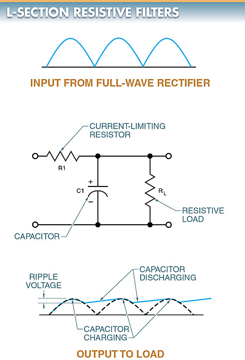
Figure 2. An L-section resistive filter circuit diagram and output waveform
L-section Inductive Filters
An L-section inductive filter is a filter that reduces surge currents by using a current-limiting inductor and a capacitor. See Figure 3.
An inductor (L1) in series opposes a change in current by creating a counter electromotive force (CEMF) or counter voltage. Surge current is greatly reduced and the capacitor charges slowly.
The inductor also aids the filtering effect of the capacitor since the CEMF of the inductor tends to cancel out the effects of the ripple voltage.
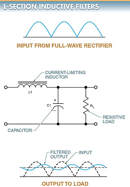
Figure 3. An L-section inductive filter circuit diagram and output waveform
The operation of an L-section inductive filter can also be seen through the effect that inductive reactance has on the circuit.
When the pulsating DC voltage is applied to the inductor, the changing voltage produces a high inductive reactance. Therefore, the inductor tends to block the pulsating DC voltage. The DC portion of the signal is allowed to pass through the inductor. The pulses not blocked by the inductor are bypassed by the capacitor.
Pi-Section Filters
A pi-section filter is a filter made with two capacitors and an inductor or resistor to smooth out the AC ripple in a rectified waveform.
Pi-section filters get their name from the Greek letter pi (π) because the filter configuration resembles the symbol for pi. The two types of pi-section filters are inductive and resistive.
A pi-section filter consists of three elements. In a pi- section inductive filter, there is a shunt input capacitor, C1; a series inductor (choke), L1; and a shunt output capacitor, C2. See Figure 4.
As the input voltage reaches the first capacitor (C1), the capacitor shunts most of the AC ripple current to the ground. This presents a much smoother current to L1. Since L1 presents a high inductive reactance to the remaining AC ripple, L1 tends to block the AC ripple much better than a resistor in a resistive pi-section filter. Finally, C2 shunts to ground any remaining AC ripple. The result is a relatively smooth DC voltage.
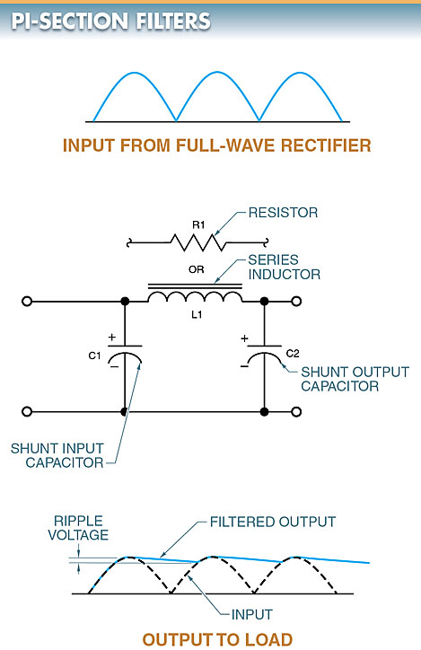
Figure 4. A pi-section filter circuit diagram and output waveform
TECH FACT
Full-wave rectifiers are used to produce unfiltered DC voltage. Filtering helps produce a purer DC voltage, but a small amount of fluctuation, called ripple, can still remain.
A 12 VDC rated power supply that fluctuates between 11.8 V and 12.2 V has a 0.4 V ripple. The lower the rated power supply ripple, the better.
DC Power Supply Filter Key Takeaways
DC power supply filters are essential for delivering stable and reliable voltage in electronic circuits by minimizing ripple and smoothing the rectified output. These filters play a critical role in ensuring the proper operation and longevity of sensitive electronic devices, making them indispensable in applications such as communication systems, medical equipment, power electronics, and precision instrumentation.