The article discusses different methods of electric motor control wiring, highlighting their advantages and disadvantages. It covers direct hardwiring, hardwiring using terminal strips, and troubleshooting techniques for motor circuits, emphasizing how these methods impact circuit modification and maintenance efficiency.
An electric motor must have a method of control in order to operate safely and efficiently. Motor control circuits vary from simple to complex.
Reversing motor control circuits, similar to no reversing motor control circuits, can be wired using manual controls (manual starters, drum switches), magnetic controls (magnetic starters), motor drives, or PLCs to control the operation of a motor.
Several different methods of wiring a motor and motor control circuit are available. These methods can be used individually or in combination to control the operation of a motor. Each motor control wiring method has advantages and disadvantages.
The four basic methods of motor control wiring are direct hardwiring, hardwiring using terminal strips, PLC wiring, and electric motor drive wiring.
Direct Hardwiring
Direct hardwiring is the oldest and most straightforward motor control wiring method used. In direct hardwiring, the power circuit and the control circuit are wired point-to-point. See Figure 1.
Point-to-point wiring is wiring in which each component in a circuit is connected (wired) directly to the next component as specified on the wiring and line diagrams. For example, the transformer X1 terminal is connected directly to the fuse, the fuse is connected directly to the stop pushbutton, the stop pushbutton is connected directly to the reverse pushbutton, the reverse pushbutton is connected directly to the forward pushbutton, and so on until the final connection from the overload (OL) contact is made back to the transformer X2 terminal.
A direct hardwired circuit may operate properly for a period of time. The disadvantage of a direct hardwired circuit is that circuit troubleshooting and circuit modification are time-consuming.
For example, when a problem occurs in a direct hardwired circuit, the circuit operation must be understood, measurements are taken, and the problem identified. Circuit operation can be understood from a wiring diagram.
Without a wiring diagram, the circuit wiring can be determined by tracing each wire throughout the circuit. The circuit problem can eventually be found; however, tracing each wire in a circuit to find the wire with a problem is time-consuming.
Time is saved as experience is gained from working on a circuit several times and understanding its operation and components.
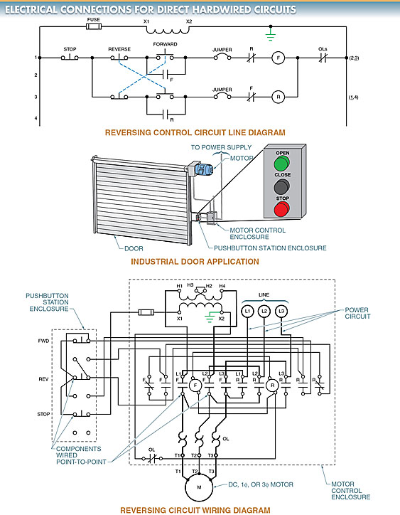
Figure 1. In direct hardwiring, the power circuit and the control circuit are wired point-to-point.
A direct hardwired circuit is difficult to modify. For example, if a forward indicator lamp and a reverse indicator lamp are to be added to a motor control circuit, their exact connection points must be found. Once the exact connection points are found, the lamps can be wired into the control enclosure. Even when the exact connection points are found, problems may arise when making the actual connection (such as there not being enough room under the terminal screw, etc.).
Some circuit modifications, such as adding forward and reverse indicator lamps, may not be a problem because they only require adding new wires. In these modifications, old wires do not need to be moved or removed.
Some circuit modifications, such as adding limit switches, are more difficult. For example, if forward and reverse limit switches are to be added to a circuit, some wiring must be removed from the circuit and/or the new wiring for the limit switches must be added. See Figure 2.
In this circuit, before the limit switches are added, the wires connecting the NC interlock contacts of the forward and reverse coils to the pushbuttons must be removed (or opened) and the limit switch wired in the opening. To do this, the technician making the circuit modification must have a wiring diagram of the circuit (or understand the circuit from past experience) in order to know which wires to open and where to locate the limit switches.
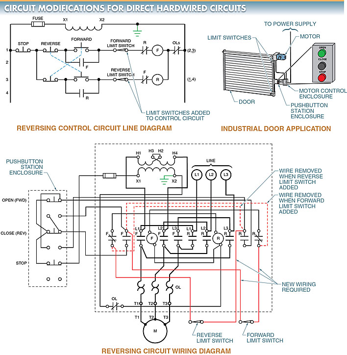
Figure 2. In direct hardwired circuits, circuit modifications may require the removal and/or addition of circuit wiring.
Hardwiring Using Terminal Strips
Hardwiring to a terminal strip allows for easy circuit modification and simplifies circuit troubleshooting.
When wiring using a terminal strip, each wire in the control circuit is assigned a reference point on the line diagram to identify the different wires that connect the components in the circuit. Each reference point is assigned a wire reference number. See Figure 3. Wire reference numbers were commonly assigned from the top left to the bottom right.
However, in most new diagrams, the power line on the left (usually L1 or X1) is assigned the number 1, and the power line on the right (usually L2 or X2) is assigned the number 2. This way the control circuit voltage can always be found at terminal 1 and at terminal 2. This aids a technician when he or she is troubleshooting a circuit. If several connections of a given number are required, jumpers can be added to the terminal strip to provide multiple connection points to one given terminal number.
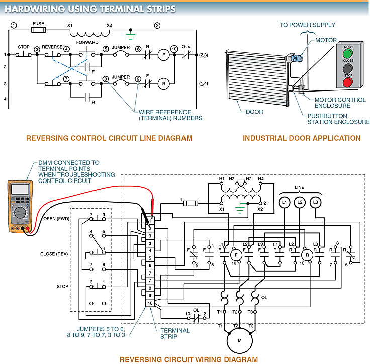
Figure 3. When hardwiring a circuit using a terminal strip, each wire in the control circuit is assigned a reference point on the line diagram to identify the different wires that connect the components in the circuit.
Troubleshooting the Motor Circuit
When troubleshooting a circuit with a terminal strip, the technician can go directly to the terminal strip and take measurements to help isolate the problem. The DMM is first placed on terminals 1 and 2. If the voltage is not correct at that point, the problem is located on the primary side of the transformer. If the voltage is correct at terminals 1 and 2, one DMM lead is left on terminal 2 and the other lead is moved to different terminals until the problem is located.
In addition to the terminal strip and wire reference numbers being an aid when troubleshooting, they also make circuit modification easier. This is because most, if not all, of the wires required to make the change, are disconnected and reconnected at the terminal strip. See Figure 4.
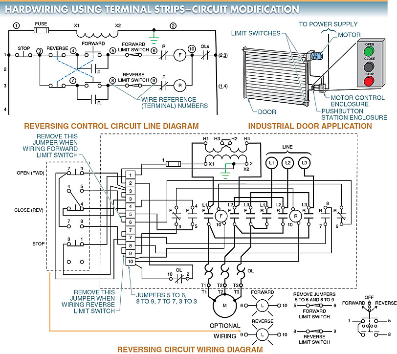
Figure 4. Terminal strips and wire reference numbers enable easy circuit modification because most wires required to make a change are disconnected and reconnected at the terminal strip.
Electric Motor Control Wiring Key Takeaways
The different methods of electric motor control wiring play a crucial role in ensuring the efficiency, safety, and adaptability of motor circuits in various applications. From direct hardwiring to terminal strip configurations, each approach offers unique advantages in terms of installation, troubleshooting, and modifications. Understanding these wiring techniques is essential for industries relying on motor-driven systems, as they impact system reliability, maintenance efficiency, and operational flexibility. Proper selection of a wiring method can streamline troubleshooting, reduce downtime, and enhance the overall performance of motor control systems, making them indispensable in both industrial and commercial settings.