The article provides an overview of different types of electric motors, focusing on single-phase and three-phase motors, their components, and common applications in commercial and industrial settings. It also covers dual-voltage three-phase motors, explaining their advantages and wiring configurations for different voltage levels.
Although there are many different types and sizes of motors, most electric motors used in commercial and industrial applications can be classified as single-phase (1 φ) or three-phase (3 φ).
Single-phase motors are commonly used in some commercial applications such as garage door openers, sump pumps, automatic doors, and ceiling fans.
Three-phase motors are commonly used in commercial and industrial applications such as freight elevators, mixing equipment, conveying equipment, HVAC equipment and material processing.
Single-Phase Motors
A single-phase (1 φ) motor is a motor that operates on single-phase electricity. Single-phase motors have two main parts, the stator and rotor. A stator is the stationary part of an AC motor that produces a rotating magnetic field. A rotor is the rotating part of an AC motor. The rotating magnetic field created by the stator rotates the rotor and shaft to deliver work. Other parts of a motor are the frame, end bells, bearings, and a fan connected to the motor shaft. See Figure 1.
Single-phase motors are commonly used in commercial and industrial applications for smaller loads, such as automatic garage doors, small drill presses, industrial vacuum systems, sump pumps, and electric conduit benders.
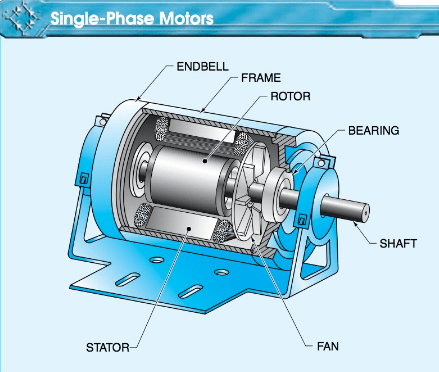
Figure 1. Single-phase motors are commonly used in applications such as automatic doors, machine and maintenance tools, and electric conduit benders.
Three-Phase Motors
A three-phase (3φ) motor is a motor that operates on three- phase electricity. Three-phase motors are used in many commercial and most industrial applications because 3 φ power is typically available in the facility and 3 φ motors are smaller, lighter, and are less likely to malfunction than 1 φ motors with similar horsepower.
Three-phase motors are more efficient in energy conversion than 1 φ motors. Three-phase motors are similar in construction to 1 φ motors. See Figure 2.
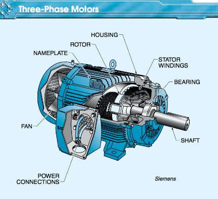
Figure 2. Three-phase motors are typically used in many commercial and most industrial applications because they are more energy efficient.
Dual-Voltage, 3 φ Motors
Most 3 φ motors are made so that they can be connected for either of two voltages. Making motors for two voltages enables the same motor to be used with two different power line voltages. A dual-voltage motor is a three-phase electric motor that is capable of operating on more than one system voltage.
A dual-voltage, 3 φ motor is the most commonly installed motor. A common dual-voltage rating is 208- 230/460 V. This type of dual-voltage rating indicates that the motor is actually rated to operate at the three different voltages of 208 V, 230 V, and 460 V.
The 208 V and the 230 V ratings are considered “low voltage” on the motor’s nameplate wiring diagram. The 460 V rating is considered to be the “high voltage” rating on the wiring diagram on the motor nameplate.
The higher voltage is preferred when a choice between voltages is available. The motor uses the same amount of power and gives the same horsepower output for either high or low voltage, but as the voltage is doubled (230 V to 460 V), current is cut in half. Using a reduced current enables the use of a smaller conductor size, which reduces the cost of motor installation.
A wiring diagram is used to show the terminal numbering system for a dual-voltage, 3 φ motor. See Figure 3. Nine leads are brought out of the motor. Leads coming out of the motor are marked T1 through T9 and can be externally connected for either of the two voltages. The terminal connections for high and low voltage are normally provided on the motor nameplate.
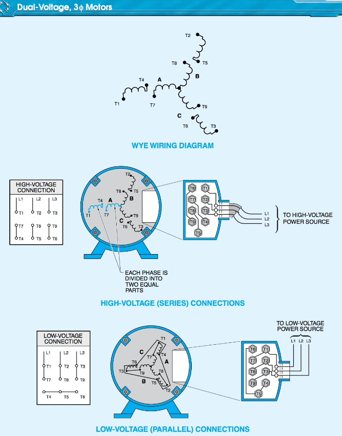
Figure 3. A dual-voltage motor is a 3φ electric motor that is capable of operating on more than one system voltage.
The nine leads are connected in either series (high voltage) or parallel (low voltage). To connect a motor for high voltage, L1 is connected to T1, L2 to T2, and L3 to T3. Lead T4 is connected to T7, T5 to T8, and T6 to T9. By connecting the leads in this configuration, the individual coils in phases A, B, and C are connected in series, with each coil receiving 50% of the line-to-neutral point voltage. The neutral point is the internal connecting point of all three phases.
Types of Electric Motors Key Takeaways
In conclusion, electric motors play a crucial role in various commercial and industrial applications, providing reliable and efficient power for numerous mechanical systems. Single-phase motors are essential for smaller applications such as garage doors and sump pumps, while three-phase motors are widely used in heavy-duty industrial equipment due to their efficiency and durability. Additionally, dual-voltage three-phase motors offer flexibility in power configurations, making them a cost-effective and versatile solution for different electrical systems.