Programmable Logic Controllers Introduction
Programmable Logic Controllers (PLC’s) were first used commercially in the 1960’s. Since then, the PLC industry has grown such that no medium to a large-scale manufacturing facility in the United States can function efficiently without them. It has created a multi-billion dollar a year industry. This includes not only sales, but also installation, programming, and field service jobs. It has impacted our lives as much as the modern personal computer or cell phone. A good technician must have an understanding of how a PLC controls automation in a plant or process to do their job. This resource will provide a basic understanding of how a PLC was developed, internal parts and software programming.
Development of the PLC
PLC’s were first developed for the automotive industry. It took hundreds of motor control panels with thousands of electromechanical relays, motor starters, pilot devices and controls to run the assembly lines on the shop floor. When a model change was warranted, production lines could be shut down for weeks while assembly lines were rewired and retooled. It took massive amounts of labor hours by skilled electricians and millwrights to get this accomplished. All this downtime and labor reduced profits for the automaker.
In the 1960’s, General Motors Corporation decided to take the lead in changing their shop floor process. The GMC Hydramatic division sought a way to automate the model changeovers. The model change had been a very labor-intensive process. Automating the process would reduce labor and downtime while increasing profits. A company named Bedford and Associates, (later named Modicon), was hired by GMC to design a way to speed up this process.
The GM engineering team designated the following criteria for the project:
- The controller had to be solid-state.
- The system had to have the flexibility of a computer system.
- Controllers had to be capable of surviving an industrial environment.
- Programming had to be easy and be able to be maintained by plant electricians.
- The system had to be reusable.
- Pricing had to be competitive with relay control systems.
- Input and Output (I/O) interfaces had to be easily replaceable.
- A modular design had to be used so that subassemblies could be easily removed, replaced and repaired.
- Manufacturing data needs to be collected and passed on to a central computing system.
- The method of programming should be in the form of relay ladder logic, a method that plant electricians, engineers, and technicians were already familiar with.
The Modicon team studied the assembly line change over process and devised a way to change the process control logic without having to rewire all the relays and panels. Modicon developed a small industrial computer called a programmable logic controller that would install in each panel. The instructions or “programs” were transmitted to each panel from a programming device. All field devices such as motor starters, relays and pilot devices were controlled by the programming of the PLC. Anytime changes were needed to the process, programs were modified and retransmitted or downloaded to the controller in the motor control panels. Rewiring of panels and relays were now obsolete for model change-overs and downtime was reduced from months to days. General Motors immediately updated their assembly plants to this new technology. This created a new era of process control.
Today, PLC’s are manufactured around the world by hundreds of different manufacturers. PLC’s are no longer limited to just the automobile industry. PLC’s are now used residentially in smart houses, heating, and air conditioning industry; as well as commercially in manufacturing, transportation, and just about every advanced process. They have evolved to become the standard for process control in any industry. Let’s take a brief look at how and why the PLC was developed by watching the following video.
Click on the link below for a short introduction to PLC’s:
PLC Hardware Components
What is a PLC and how do PLC’s work?
A PLC is an industrial computer that reads the inputs of a process and makes decisions based on the programmed logic to control the outputs of a process.
PLC’s consist of a few different components; Input and output modules (I/O), a Power Supply, Programming Device and a Central Processing Unit (CPU). The CPU also has memory for logic functions and data tables for I/O storage and will be covered later. So, let’s start at the beginning and define exactly what inputs and output are and how they interact with a PLC.

Figure 2- PLC System
PLC Input and output modules (I/O)
Inputs and Outputs can be digital or analog, depending on the field device needed. An input is a field device that updates the PLC on how the process is running. An input field device could be a pushbutton switch, pressure sensor, or photo sensor to name a few. There are hundreds of types of inputs that monitor a process and report the data back to the PLC. The input field device tied to the PLC is not controlled; only read by the PLC to update the status of the process input. These inputs can be of different signal types, such as 4-20 milliamps, 24 volts-dc, or 110 volts-ac. A PLC is versatile enough to accept multiple signal types by having different input cards installed that accept these signals.
An output is a command supplied by the CPU Logic to control an output field device. These field devices may include, relays, timers, motor starters, lights, counters or displays. The output command is driven by the updated input tables, the CPU logic, and a signal sent to the output field device to be controlled.
These inputs and outputs are not directly connected to the PLC; therefore, if one failed or shorted electrically, it may short-circuit the entire PLC. A protection system was put into place to prevent this from happening with both inputs and outputs. These field devices are connected to an input/output card which has opto-isolators installed.
The opto-isolator transfers the input signal through circuitry to a signal the PLC can understand. Likewise, the output card works just the opposite of an input card. It converts the PLC language into a signal that is useable for an output field device. This is usually accomplished by an LED (light emitting diode) giving off light when an input signal is active. The light is then detected by a photo diode and converted into a useable signal for the PLC. Input tables are updated continuously and outputs can be changed in real time as the program is scanned for changes from the input field devices and processed to an output.
Click on the short movie below to understand how input and output modules work.
How Input and Output Modules Work
Programming Device
Programming devices are a way for the programmer to write and load the program. Programming Devices may also be used to monitor the I/O and the process in real time and for troubleshooting when the process doesn’t function correctly. There are different types of Programming devices.
Early on, hand-held programming devices were used. They were about the size of a scientific calculator and only displayed one line of code at a time. Today the PC or laptop is the most widely used programming device. Multiple lines of code may be viewed on one screen. Human Machine Interface’s (HMI’s) are becoming very popular for process monitoring and troubleshooting on the shop floor. Most are programmed for a visualization of the process in real time and are about the size of a laptop screen. Process values can be changed on the touch screen HMI or multiple screens can be programmed for different process attributes; such as monitoring, troubleshooting, process history or alarms.
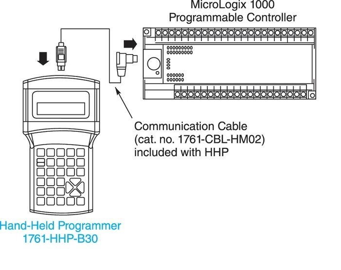
Figure 3 – Handheld Programming Device (Courtesy of Rockwell Automation, Inc.)
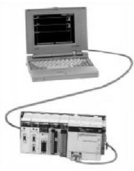
Figure 4 – Laptop Programming Device
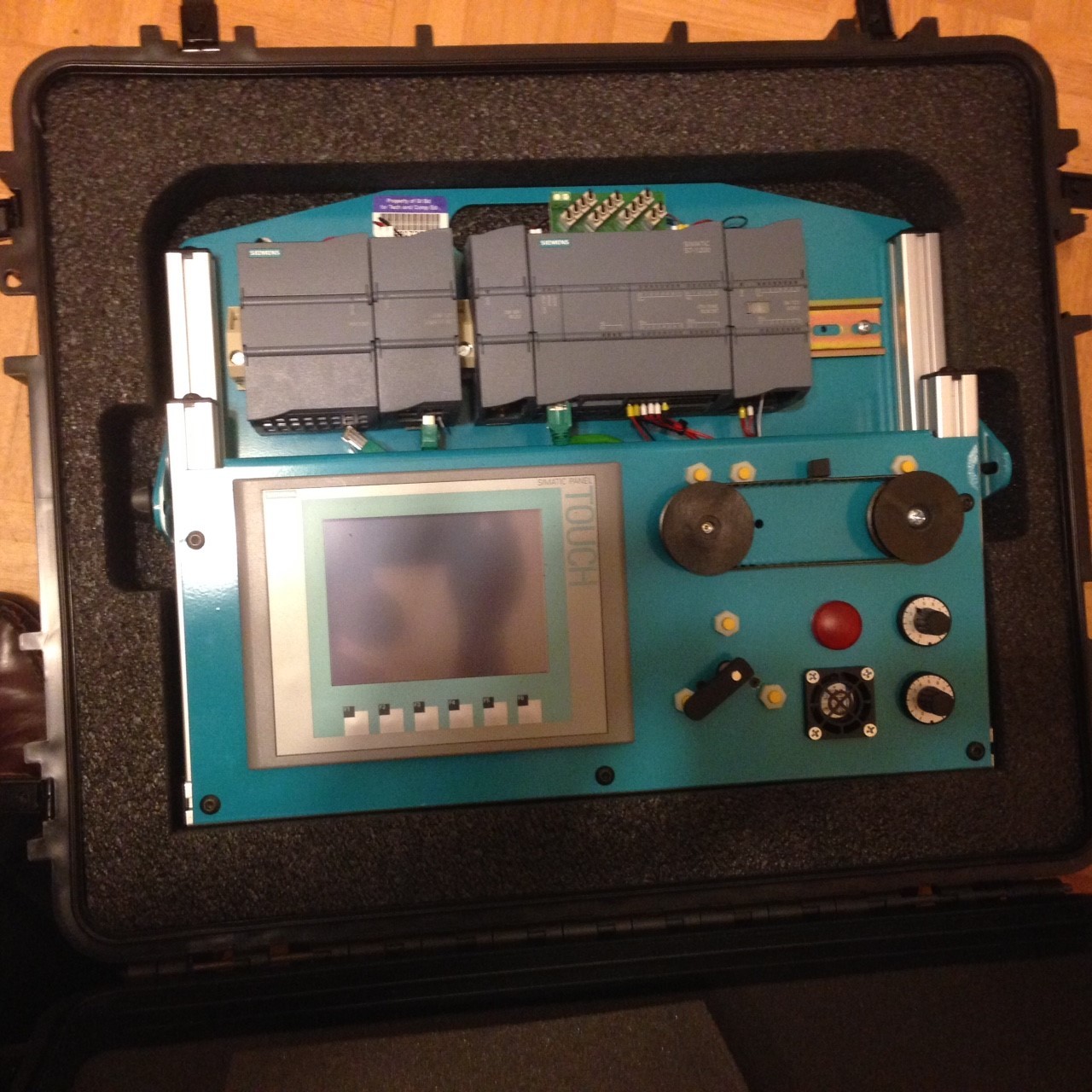
Figure 5 – HMI Screen on PLC Trainer-SCC
PLC Power Supply
The Power Supply provides different voltage sources that are required for the different field devices, CPU, and internal memory operations. The power supply usually requires 110 volts ac. From this point, the power is filtered for any electrical interference and isolated to internal PLC components. It is then converted to a lower voltage or rectified into the direct current as needed. The power supply may be used to power external inputs and outputs, depending on the application.
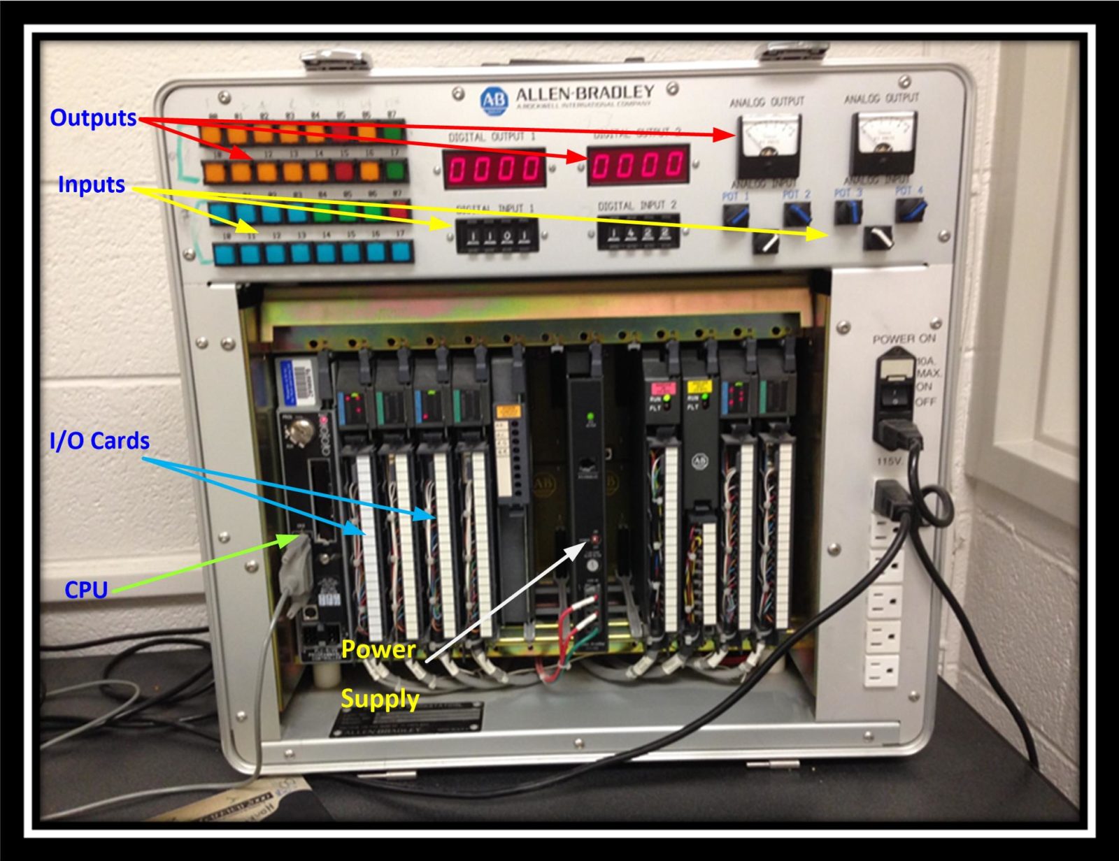
Figure 6 – PLC System with Power Supply
PLC Central Processing Unit (CPU)
The Central Processing Unit provides all the logic functions as well as directing communication flow with other components; both internal and external. It is the “brain” of the PLC. Internally, the CPU provides data space to store the program instructions. It also performs math, counting and timing functions based on the program logic. Externally, the CPU updates the input file status from field devices and executes the appropriate output function.