The article explains the fundamental concepts of single-phase and three-phase electric power systems, their generation, distribution, and applications. It also covers related topics such as the advantages of three-phase systems, transformer configurations, and electrical power types including true, reactive, and apparent power, along with the concept of power factor in AC circuits.
Single-phase ac voltage is generated in some smaller renewable energy systems. Power companies almost universally generate three-phase (3φ) ac electric power, and they supply it to industries as three-phase or convert it to single-phase (1φ) for residential and small commercial operations.
Larger industrial users use the three-phase ac directly for powering motors and other industrial components. Three-phase is covered in detail in this section because of its importance in the power grid.
Single-Phase AC Basics
As you know, ac is a sinusoidal waveform, which means it has the shape of the mathematical definition of a sine wave. It is common practice to refer to electrical waveforms with this shape as sine waves.
An ac voltage can be specified as peak voltage, peak-to-peak voltage, or root-mean-square (rms) voltage.
The frequency of the wave is defined as the number of cycles that occur in 1s and is given the units of Hertz (Hz). For example, if 1,000 cycles occur in 1 s, the frequency is 1 kHz. The reciprocal of frequency is called the period and has units of time. Thus, a 1 kHz frequency has a period of 1 ms.
The frequency of electrical energy is determined by the generator or inverter that produces it. Generally, the frequency distributed by power companies is 50 Hz or 60 Hz, depending on the country (and, in some cases, by the region within the country).
In some specialized applications, other frequencies are used. On military ships and planes, 400 Hz is common for radio and electronic systems.
In some countries, low-frequency ac (162⁄3 Hz and 25 Hz) is used for electric trains in order to reduce reactive losses in overhead lines and improve commutation in the large series motors used in locomotives.
Lower frequencies were originally supplied by large rotary frequency converters, but today they can be supplied with static frequency converters.
In residential and smaller commercial uses, the voltage supplied by the utility company is single-phase voltage (1φ), which means it has only one continuously varying sinusoidal waveform.
The minimum requirement to deliver single-phase ac is only two wires, but it is standard in North America for the utility company to supply two “hot” wires of opposite polarity and a neutral wire, which is the current carrying return wire. This configuration of two hot wires and a neutral is referred to as split-phase.
In North America, the voltage from each hot wire to neutral is 120 V, and between the two hot wires, it is 240 V.
The 240 V is used on larger appliances, such as air conditioners and clothes dryers, and the lower voltage is used on smaller appliances and lighting.
In much of the rest of the world, the standard varies from 220 V to 240 V at 50 Hz. Some of these countries also have a lower voltage available.
Single-phase voltage is used in residential and in commercial applications because it is less expensive to distribute than three-phase power.
The loads for residential and small commercial establishments are typically small (lights, appliances, etc.) and they are designed for low-voltage, single-phase.
Definition of Three-Phase Voltage
Recall that the term three-phase refers to three ac voltages that have the same magnitude but are separated by 120°. Figure 1a illustrates a three-phase voltage.
The first phase is called phase A, the second phase is called phase B, and the third phase is called phase C. Phase B is 120° shifted from phase A, and phase C is shifted another 120°. Figure 1b represents the same waveforms but drawn as a phasor diagram.
A phasor is a rotating vector, which is a quantity with magnitude and direction. Phasors allow basic trigonometry relationships to be applied to sinusoidal waves.
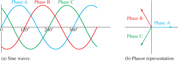
Figure 1 Three-Phase Voltage
Advantages of Three-Phase Systems
- In general, three-phase voltage is more economical to produce and transmit than is single-phase, so most generating and transmission systems are three-phase.
- Three-phase voltage is stepped up to very high voltages to be transmitted over long distances. The higher transmission voltages cause current to be lower. For this reason, conductors can be smaller and weigh less, resulting in net savings to the utility company.
- In a few cases, very high voltage dc has been used for very long transmission lines, but the conversion process from ac to dc and back is expensive and rarely done.
- For industrial applications, three-phase voltage is applied directly to motors and some other circuits.
- When a three-phase voltage is used to power motors, it creates a rotating magnetic field that allows the motor to produce high torque to move loads on its shaft, without the need for separate starting windings.
- Because the three-phase voltage has a phase shift of 120° between each pair in its three phases, it can create a rotating magnetic field when it is applied to the stator of three-phase motors. The rotating magnetic field causes the rotor to spin.
- Three-phase ac motors have other advantages: They are simpler to maintain, and they use smaller wiring than comparable single-phase motors and do not need special starting circuits, so they are widely used in industries that require a lot of motors.
Three-Phase in Power Systems
In almost all commercial power generators, three-phase ac is generated at the source. The generator can be turned by a wind turbine, steam turbine, or another prime mover.
Because maintaining the exact frequency is critical, wind turbines may use a power electronic frequency converter.
In solar energy systems that use photovoltaic panels, dc is produced by the system. In this case, the dc is sent through an inverter that converts it to ac.
In large systems, the ac is a three-phase voltage that can be connected to the grid for transmission to end users.
Single-phase voltage is derived from three-phase voltage. Converting three-phase to single-phase can be done in different ways.
A common conversion method is from a delta (Δ) connected transformer. The delta configuration is a three-phase wiring method named for the Greek letter delta and takes its triangular shape in diagrams.
In North America, the center-tap from one winding of a delta connection is neutral (N). Across each winding in the secondary is 240 V, so the voltage from the center-tap to the coil ends is 120 V (Figure 2).
The corners of the delta are the connection points for the three-phase output and are identified as L1, L2, L3. In this case, only L1, L2, and N are taken for the output to a single-phase customer.
Industrial locations can have all four wires (L1, L2, L3, and N) brought out in order to have 120 V, 240 V, and 3φ 240 V available for large three-phase motors (this configuration is called a four-wire delta).
It is important that L3 is not used with the N. This combination would produce 208 volts, which is not used in residential applications because it could load the transformer unevenly and possibly cause overheating.
The L3 wire is marked with an orange color so that it can be identified and used only for three-phase.
Although 208 V is used in some industrial applications, it is developed from a wye connected transformer instead of a delta connected transformer.
The wye configuration is a three-phase wiring method that is named for the letter Y because its diagram is shaped like the letter Y.
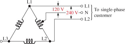
Figure 2 Conversion of Three-Phase to Single-Phase Using a Center-Tapped Secondary on a Delta-Wired Transformer
True Power, Apparent Power, and Reactive Power
Power is a fundamental concept in electrical work and many renewable energy systems.
The power in a purely resistive circuit can be calculated by multiplying voltage by current. Power in purely resistive circuits is sometimes referred to as true power (Ptrue), and it is measured in watts.
True power is the actual power dissipated in a circuit, usually in the form of heat. Most loads are not purely resistive.
If the load has inductance or capacitance, the current and voltage shift in phase with respect to each other, depending on the amount of resistance and reactance present.
Reactive power (Pr) is the rate at which energy is stored and alternately returned to the source by a capacitor or an inductor. It is measured in units of volt-amps-reactive (VAR).
Reactive power is “borrowed” power; it shuttles back and forth between the source and the load but does no useful work.
In a reactive component, you can calculate the reactive power by finding the product of voltage across the component and current in the component (ignoring any resistive loss).
Most practical loads are not purely resistive or purely reactive but are a combination of both. In this case, the product of rms voltage and rms current without regarding phase differences is called the apparent power (Pa).
Apparent power is measured in units of volt-amps (VA) to distinguish it from true power and reactive power. Apparent power is always equal to or larger than true power.
Apparent power is the power that appears to be transferred between the source and the load, and it consists of two parts: One part is the true power that is actually dissipated, the other is the reactive part that tends to shift the phase.
Motors act like an inductive load. You may see on a motor nameplate the units for power as VA because it is specified as apparent power.
Power Factor
Power factor applies to inverters in single-phase circuits. It was defined in terms of the phase angle between current and voltage (PF = cos θ where θ = the phase angle between voltage and current).
An equivalent definition that is useful is to define it in terms of the ratio of true power to apparent power.
For an induction motor, the power factor changes with the load, so it is normally specified under full load. The equation for power factor written as a ratio of two powers is:
\[PF=\frac{{{P}_{true}}}{{{P}_{a}}}\]
Where
PF = power factor
Ptrue = true power, in W
Pa = apparent power, in VA
Power Factor Calculation Example
Determine the power factor for a circuit if the true power is 1.56 kW and the apparent power is 1.84 kVA.
Solution:
\[PF=\frac{{{P}_{true}}}{{{P}_{a}}}=\frac{1.56kW}{1.84kVA}=0.847\]
Expressed as a percentage, the PF is 84.7%.
Three-Phase Power Basics
The total power delivered to a three-phase load is more complicated because of the phase shifts in the circuit. You can find total power delivered to a balanced load if you know the voltage between two lines and the current in one line.
The product of line voltage and line current is the apparent power, Pa. The total power is given by:
\[{{P}_{total}}=\sqrt{3}(PF){{P}_{a}}\]
Where
Ptotal has the units of watts or kilowatts (W or kW)
Example
A three-phase motor is running on 480 V and has a line current of 51.5 A.
- Determine the apparent power.
- If the power factor is 0.95, determine the total power supplied from the source.
Solution
$\begin{align} & a.\text{ }{{P}_{a}}~=~VI~=\left( 480\text{ }V \right)\left( 51.5\text{ }A \right)\text{ }=~24.7\text{ }kVA \\ & b.\text{ }{{P}_{total}}~=\text{ }\sqrt{3}\left( 0.95 \right)\left( 27.7\text{ }kW \right)\text{ }=~40.7\text{ }kW \\\end{align}$
Review Questions
- What is split-phase?
- How do you label the three wires that supply 120/240 V single-phase in North America?
- What are the major advantages of three-phase voltage to utilities?
- Why is a three-phase motor more efficient than a single-phase motor?
- What is the difference between true power and apparent power?
- What is power factor? What units are used to represent it?
Answers:
- An electrical delivery method whereby two “hot” wires of opposite polarity and a neutral are supplied to the user from the power utility
- L1 (line 1), L2 (line 2), and N (neutral)
- It is more efficient to produce and transmit than single-phase voltage.
- It can create a rotating magnetic field without starting windings and it can use smaller wiring than comparable single-phase motors.
- True power is always dissipated in the circuit; apparent power is the product of the voltage times the current, expressed in volt-amps and includes resistive and reactive components.
- The ratio of true power to apparent power; it is dimensionless.
Three Phase Electric Power Key Takeaways
Understanding the distinctions and functionalities of single-phase and three-phase AC systems, along with the principles of true, reactive, and apparent powers, is essential for efficient design, operation, and optimization of electrical and industrial systems. These concepts are not only foundational in residential and commercial electricity distribution but are also critical in powering industrial machinery, managing energy efficiency, and integrating renewable energy sources into the power grid. The ability to calculate and interpret power factor, for example, helps in minimizing energy losses and improving system performance.