The article discusses the two main types of AC generators: single-phase and three-phase AC generators. It explains their operation, including the generation of alternating current through armature rotation, and details the different connections used in three-phase generators (wye and delta) along with their impact on voltage and power distribution.
The types of AC generators include single-phase (1φ) and three-phase (3φ) AC generators. Single-phase and three-phase AC generators operate similarly; however, single-phase generators have one armature and three-phase generators have three armatures. Three-phase generators provide a more consistent voltage than single-phase generators. Three-phase AC generators are either wye-connection or delta-connection.
Single-Phase AC Generator Operation
Each complete rotation of the armature in a single-phase (one wire) AC generator produces one complete alternating current cycle. See Figure 1.
In position A, before the armature begins to rotate in a clockwise direction, there is no voltage and no current in the external (load) circuit because the armature is not cutting across any magnetic lines of force (0° of rotation).
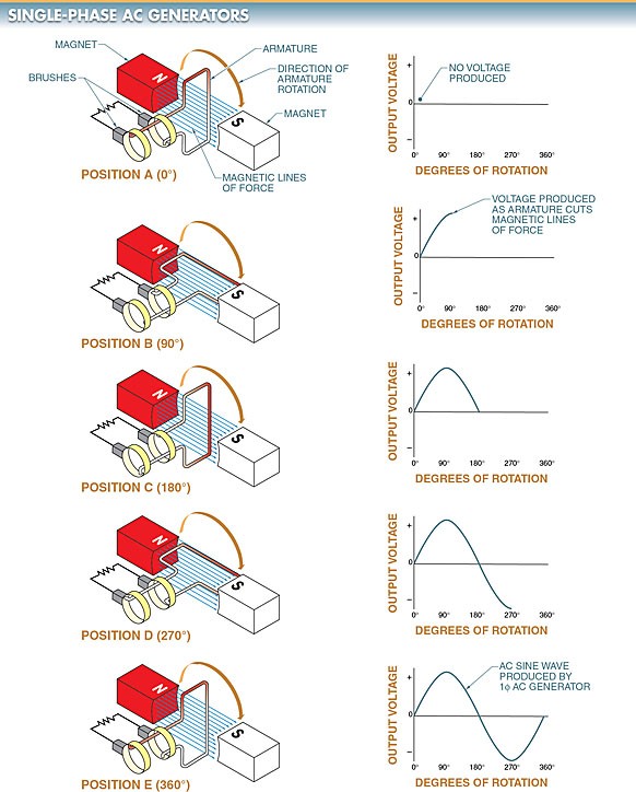
Figure 1. In a 1φ AC generator, as the armature rotates through 360° of motion, the voltage generated is a continuously changing AC sine wave.
As the armature rotates from position A to position B, each half of the armature cuts across the magnetic lines of force, producing current in the external circuit. The current increases from zero to its maximum value in one direction. This changing value of current is represented by the first quarter (90° of rotation) of the sine wave.
As the armature rotates from position B to position C, current continues in the same direction. The current decreases from its maximum value to zero. This changing value of current is represented by the second quarter (91° to 180° of rotation) of the sine wave.
As the armature continues to rotate to position D, each half of the coil cuts across the magnetic lines of force in the opposite direction. This changes the direction of the current. During this time, the current increases from zero to its maximum negative value. This changing value of current is represented by the third quarter (181° to 270° of rotation) of the sine wave.
As the armature continues to rotate to position E (or position A again), the current decreases to zero. This completes one 360° cycle of the sine wave.
Three-Phase AC Generator Operation
The principles of a three-phase (3φ) AC generator are the same as a 1φ AC generator except that there are three equally spaced armature windings 120° out of phase with each other. See Figure 2. The output of a 3φ AC generator results in three output voltages 120° out of phase with each other.
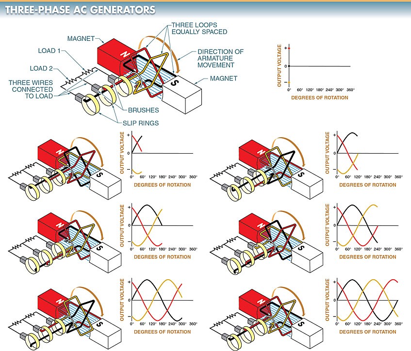
Figure 2. A 3φ AC generator has three equally spaced armature windings 120° out of phase with each other.
A 3φ AC generator has six leads coming from the armature coils. When these leads are brought out from the generator, they are connected so that only three leads appear for connection to the load.
Armature coils can be connected in a wye (Υ) connection or a delta (∆) connection. The manner in which the leads are connected determines the electrical characteristics of the AC generator output. See Figure 3.
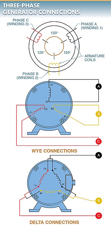
Figure 3. When the six leads of a 3φ AC generator are brought out, they are connected in a delta connection or a wye connection.
Wye (Y) Connections. A wye (Y) connection is a connection that has one end of each coil connected together and the other end of each coil left open for external connections. This circuit can be simplified by connecting the A2, B2, and C2 phase ends together. See Figure 4.
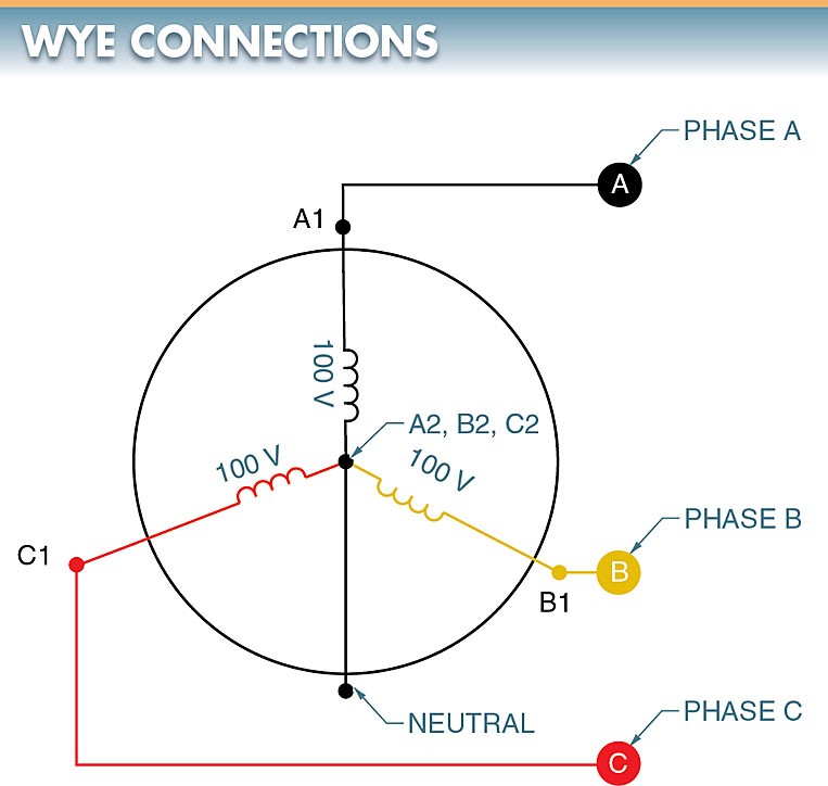
Figure 4. A common neutral wire can safely connect the internal leads of a wye-connected alternator to form a common return for lighting loads.
The three ends can be safely connected at the neutral point because no voltage difference exists between them. As phase A is at its maximum, phases B and C are opposite to A. If the equal opposing values of B and C are added vectorially, the opposing force of B and C combined is exactly equal to A. See Figure 5.
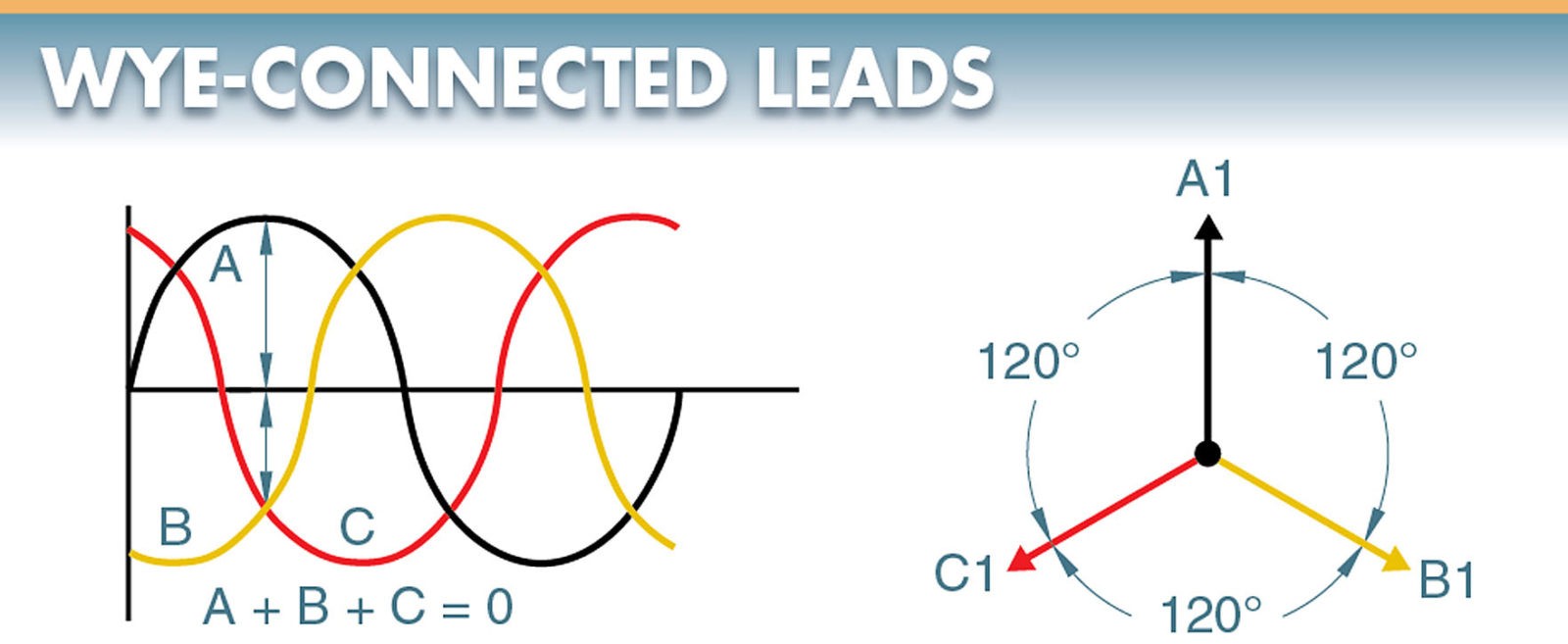
Figure 5. The 3φ voltages of a wye-connected alternator effectively cancel each other at the neutral point, allowing the three leads of the alternator to be connected.
The net effect is a large voltage (pressure) difference between the A1, B1, and C1 coil ends, but no voltage difference between the A2, B2, and C2 coil ends. The common wire (lead) may or may not be connected from the generator. If it is connected, it is called the neutral.
A simplified drawing shows a wye-connected generator with the common wire or neutral not being connected outside the generator. In this configuration, each load is connected across two phases in series. The voltage between any two lines in a wye-connected AC generator is 1.73 (√3) multiplied by any of the individual phase voltages. If the 1φ voltage is 100 V, then the voltage between any two lines in the wye configuration will be 173 V (100 × 1.73). Since both coils are in series, the current remains the same throughout the coils.
Another way to look at the output voltage of an AC generator is by using vectors. A vector is used to show magnitude and direction. A vector can be visualized as an arrow drawn in a specific direction, with a length that is equal to the magnitude (voltage or current) drawn in a specific direction. See Figure 6.
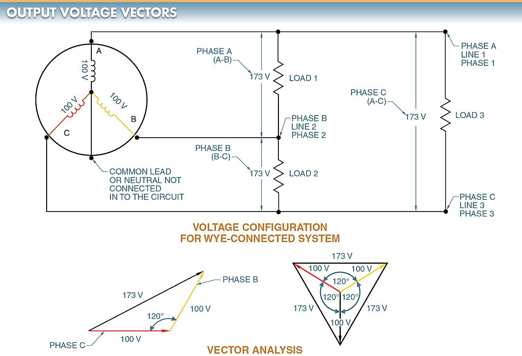
Figure 6. Vectors can be used to illustrate the magnitude and direction of AC generator output voltages.
The voltage measured across a single winding or phase is known as the phase voltage. The voltage measured between the lines is known as line-to-line voltage or, simply, the line voltage. When referring to the wiring schematics, terms such as Phase A, Phase 1, and Line 1 are often used interchangeably.
A light can be connected to each separate phase of a wye-connected AC generator. Each light illuminated from the generated 1φ power is delivered from each phase. The A2, B2, and C2 wires return to the generator together.
In a 3φ wye-connected lighting circuit, the 3φ circuit is balanced because the loads are all equal in power consumption. In a balanced circuit, there is no current flow in the neutral wire because the sum of all currents is zero.
All large power distribution systems are designed as 3φ systems with the loads balanced across the phases as closely as possible. The only current that flows in the neutral wire is the unbalanced current. This is normally kept to a minimum because most systems can be kept fairly balanced. The neutral wire is normally connected to a ground such as the earth.
A wye connection can be used to obtain phase-to- neutral voltage (1φ low voltage), phase-to-phase voltage (1φ high voltage), and phase-to-phase-to-phase voltage (3φ voltage). See Figure 7. Phase-to-phase voltage is also referred to as line voltage.
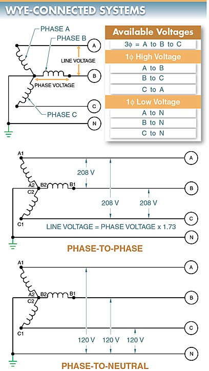
Figure 7. In wye-connected systems, the neutral wire is connected to the ground and has various available voltages.
In a 3φ wye-connected system, the phase-to-neutral voltage is equal to the voltage generated in each coil. For example, if a generator produces 120 V from A1 to A2, the equivalent 120 V is present from B1 to B2 and C1 to C2. Thus, in a 3φ wye-connected system, the output voltage of each coil appears between each phase and the neutral.
In a high-voltage, wye-connected AC generator such as those found in power plants, a phase-to-neutral voltage of 2400 V creates a phase-to-phase voltage of 4152 V, and a phase-to-neutral voltage of 7200 V creates a phase-to-phase voltage of 12,456 V.
One of the benefits wye-connected systems bring to a utility company is that even though their generators are rated at 2400 V or 7200 V per coil, they can transmit at these higher phase-to-phase voltages with a reduction in losses. This is because the higher the transmitted voltage, the lower the power loss.
According to the formula P = E × I, power equals voltage multiplied by current. When the voltage is higher, the current is lower for a given amount of power.
According to the formula, P = I2 × R, power (or power loss) equals current squared multiplied by resistance. With a lower current, there is a lower power loss for a power line with a given resistance. Therefore, power lines can carry more power at higher voltages than at lower voltages. The reduction in power losses across transmission lines is especially important for long rural power lines.
Delta (∆) Connections. A delta (∆) connection is a connection that has each coil end connected end-to-end to form a closed loop. Alternator coil windings of a 3φ system can also be connected as a delta connection. See Figure 8. As in a wye-connected system, the coil windings are spaced 120° apart.
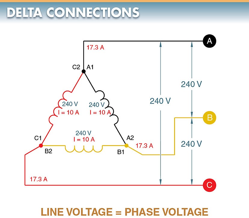
Figure 8. A delta connection has each coil end connected end-to-end to form a closed loop.
In a delta-connected system, the voltage measured across any two lines is equal to the voltage generated in the coil winding. This is because the voltage is measured directly across the coil winding. For example, if the generated coil voltage is equal to 240 V, the voltage between any two lines equals 240 V. In the delta configuration, line voltage and phase voltage are the same.
Following any line in a delta-connected system back to the connection point shows that the current supplied to that line is supplied by two coils. Phase A can be traced back to connection point A1, C2. However, as in a wye-connected system, the coils are 120° apart. Therefore, the line current is the vector sum of the two coil currents.
In a balanced system, the phase currents are equal. In a balanced 3φ delta-connected system, the line current is equal to 1.73 times the current in one of the coils.
For example, it is assumed that each of the phase windings in a delta-connected system has a current flow of 10 A. The current in each of the lines, however, is 17.32 A. The reason for this difference in current is that current flows through different windings at different times in a 3φ circuit. During some periods, the current will flow between two lines only. At other times, the current will flow from two lines to the third line.
The delta connection is similar to a parallel connection because there is always more than one path for current flow. Since these currents are 120° out of phase with each other, vector addition must be used when finding the sum of the currents. See Figure 9.
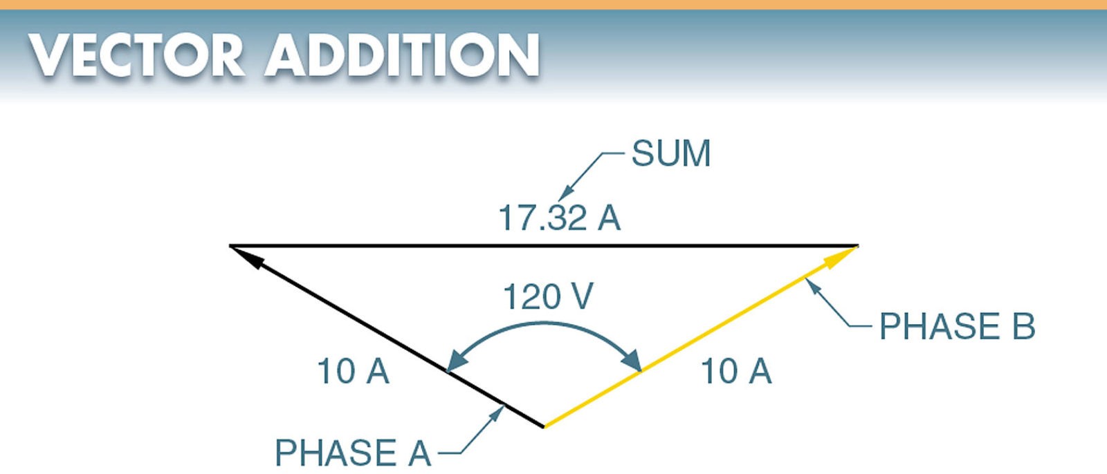
Figure 9. Vectors may be added to find the sum of currents and voltages that are out of phase.
Tech Tip
Some old delta-connected systems have one power line grounded, producing a corner-grounded system. Corner-grounded delta-connected systems are no longer used because they can cause a dangerous situation if unrecognized. A digital multimeter (DMM) set to measure voltage should read the same from each phase to ground. If not, the system is a corner-grounded delta-connected system, or power is interrupted on one leg.
AC Generators Key Takeaways
AC generators, whether single-phase or three-phase, play a crucial role in various applications, from household electricity supply to industrial power distribution. Single-phase generators are commonly used in residential and small commercial settings, providing a reliable power source for appliances and lighting. In contrast, three-phase generators are essential in large-scale industrial operations, ensuring efficient power transmission and minimizing energy losses through balanced load distribution. The wye and delta connections in three-phase generators further optimize voltage regulation and current flow, making them indispensable in power grids, manufacturing, and heavy machinery.