The article provides a comprehensive overview of AC motor types, including single-phase and three-phase motors, their working principles, and key components. It covers various single-phase motor types (shaded-pole, split-phase, and capacitor motors), three-phase motors, their advantages, applications, and related control and circuit diagrams.
This comprehensive guide covers Single Phase Motor (Shaded-Pole, Split-Phase, Capacitor Start, Capacitor Run, Capacitor Start and Run Motors) and Three Phase Motor (Single-Voltage Three Phase Motor and Dual Voltage Three Phase Motor) types, their working principles and relevant control and circuit diagrams in details.
Alternating current (AC) motors are the most common type of motor used to produce work. AC motors range in size from fractional horsepower (HP) to thousands of HP.
Fractional HP AC motors are used in residential buildings to drive refrigerators, washing machines, and dryers; circulate air, and operate appliances.
Larger AC motors are used in commercial buildings to drive large appliances such as HVAC systems, commercial washers and dryers, elevators/escalators, and baggage carousels at airports.
AC motors of all sizes are used in industrial applications to produce food and other consumable products; operate mining equipment; pump water, sewage, and petroleum; and provide instantaneous work for any application that requires a safe and efficient power source.
Since all AC motors operate on the same basic principles, understanding their operation, abilities, and limits is important when designing, installing, servicing, and troubleshooting any system that includes a motor.
AC Motor Types
An alternating current (AC) motor is a motor that uses alternating current to produce rotation. AC motors have several advantages over DC motors.
One advantage is that AC motors have only two bearings that can wear. Secondly, there are no brushes to wear because the motor does not have a commutator. For these reasons, maintenance is minimal. Also, no sparks are generated to create a hazard in the presence of flammable materials.
The main parts of an AC motor are the rotor and stator. A rotor is the rotating part of an AC motor. A stator is the stationary part of an AC motor. See Figure 1. AC motors are either single-phase (1φ) or three-phase (3φ).
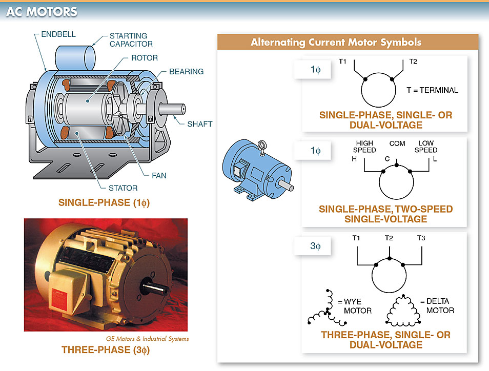
Figure 1. The main parts of an AC motor are the rotor and stator.
Single-Phase Motors
Single-phase motors are used in residential applications for AC motor-driven appliances such as furnaces, air conditioners, washing machines, etc. Single-phase motors include shaded-pole, split-phase, and capacitor motors.
Shaded-Pole Motors
A shaded-pole motor is a single-phase AC motor that uses a shaded stator pole for starting. Shading the stator pole is the simplest method used to start a single-phase motor. Shaded-pole motors are commonly 1/20 HP or less and have low starting torque.
Common applications of shaded-pole motors include small cooling fans found in computers and home entertainment centers.
Shaded Pole Motor Working
The shaded pole is normally a solid single turn of copper wire placed around a portion of the main pole laminations. See Figure 2.
The shaded pole delays the magnetic field in the area of the pole that is shaded. Shading causes the magnetic field at the pole area to be positioned approximately 90° from the magnetic field of the main stator pole.
The offset magnetic field causes the rotor to move from the main pole toward the shaded pole. This movement determines the starting direction of a shaded-pole motor.
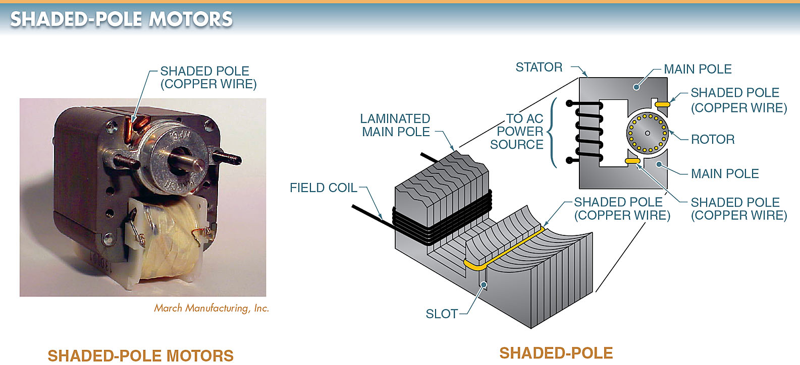
Figure 2. A shaded-pole motor uses a shaded stator pole, which is normally a solid single turn of copper wire.
Split-Phase Motors
A split-phase motor is a single-phase AC motor that includes a running winding (main winding) and a starting winding (auxiliary winding). Split-phase motors are AC motors of fractional horsepower, usually 1/20 HP to 1/3 HP.
Split-phase motors are commonly used to operate washing machines, oil burners, and small pumps and blowers.
Split Phase Motor Parts
A split-phase motor has a rotating part (rotor), a stationary part consisting of the running winding and starting winding (stator), and a centrifugal switch that is located inside the motor to disconnect the starting winding at approximately 60% to 80% of full-load speed. See Figure 3.
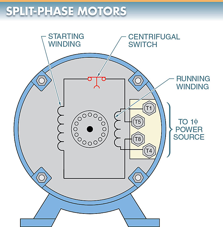
Figure 3. A split-phase motor includes a running winding, a starting winding, and a centrifugal switch.
Split Phase Motor Working
When starting, both the running windings and the starting windings are connected in parallel. The running winding is normally made up of heavy insulated copper wire, and the starting winding is made of fine insulated copper wire.
When the motor reaches approximately 75% of full speed, the centrifugal switch opens, disconnecting the starting winding from the circuit. This allows the motor to operate on the running winding only.
When the motor is turned off (power removed), the centrifugal switch recloses at approximately 40% of full-load speed.
Running Winding
The running winding is made of larger wire and has a greater number of turns than the starting winding. When the motor is first connected to power, the reactance of the running winding is higher and the resistance is lower than the starting winding.
Reactance is the opposition to the flow of alternating current in a circuit due to inductance.
Starting Winding
The starting winding is made of relatively small wire and has fewer turns than the running winding. When the motor is first connected to power, the reactance of the starting winding is lower and the resistance is higher than the running winding.
When power is first applied, both the running winding and the starting winding are energized. The running winding current lags the starting winding current because of its different reactance. This produces a phase difference between the starting and running windings.
A 90° phase difference is required to produce maximum starting torque, but the phase difference is commonly much less. A rotating magnetic field is produced because the two windings are out of phase.
The rotating magnetic field starts the rotor rotating. With the running and starting windings out of phase, the current changes in magnitude and direction, and the magnetic field moves around the stator. This movement forces the rotor to rotate with the rotating magnetic field.
Capacitor Motors
A capacitor motor is a single-phase AC motor that includes a capacitor in addition to the running and starting windings. Capacitor motor sizes range from 1/8 HP to 10 HP. Capacitor motors are used to operate refrigerators, compressors, washing machines, and air conditioners.
Capacitor Motor Construction
The construction of a capacitor motor is similar to that of a split-phase motor, except that in a capacitor motor, a capacitor is connected in series with the starting winding.
The addition of a capacitor in the starting winding gives a capacitor motor more torque than a split-phase motor.
The three types of capacitor motors are capacitor-start, capacitor-run, and capacitor start-and-run motors.
Capacitor Start Motor
A capacitor-start motor operates much the same as a split-phase motor in that it uses a centrifugal switch that opens at approximately 60% to 80% of full-load speed.
In a capacitor-start motor, the starting winding and the capacitor are removed when the centrifugal switch opens. The capacitor used in the starting winding gives a capacitor-start motor high starting torque. See Figure 4.
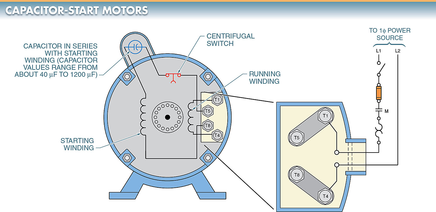
Figure 4. A capacitor-start motor has a capacitor in the starting winding, which gives the motor a high starting torque.
Capacitor-Run Motor
A capacitor-run motor has the starting winding and capacitor connected in series at all times.
A lower- value capacitor is used in a capacitor-run motor than in a capacitor-start motor because the capacitor remains in the circuit at full-load speed. This gives a capacitor-run motor medium starting torque and a somewhat higher running torque than a capacitor-start motor. See Figure 5.
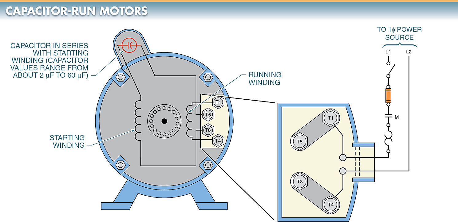
Figure 5. A capacitor-run motor has the starting winding and capacitor connected in series at all times.
Capacitor Start-And-Run Motor
A capacitor start-and-run motor uses two capacitors. A capacitor start-and-run motor starts with one value capacitor in series with the starting winding and runs with a different value capacitor in series with the starting winding.
Capacitor start-and-run motors are also known as dual-capacitor motors. See Figure 6.
A capacitor start-and-run motor has the same starting torque as a capacitor-start motor. A capacitor start and run motor has more running torque than a capacitor-start motor or capacitor-run motor because the capacitance is better matched for starting and running.
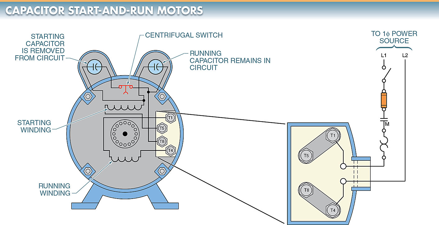
Figure 6. In a capacitor start-and-run motor, the starting capacitor is removed when the motor reaches full-load speed, but the running capacitor remains in the circuit.
In a typical capacitor start-and-run motor, one capacitor is used for starting the motor and the other capacitor remains in the circuit while the motor is running.
A large-value capacitor is used for starting and a small-value capacitor is used for running. Capacitor start-and-run motors are used to run refrigerators and air compressors.
Three-Phase Motors
Three-phase motors are the most common motors used in industrial applications. Three-phase motors are used in applications ranging from fractional horsepower to over 500 HP.
Three-phase motors are used in most applications because they are simple in construction, require little maintenance, and cost less to operate than the single-phase or DC motors. The most common three-phase motor used in most applications is the induction motor.
An induction motor is a motor that has no physical electrical connection to the rotor. Induction motors have no brushes that wear or require maintenance. Current in the rotor is induced by the rotating magnetic field of the stator.
In a three-phase motor, a rotating magnetic field is set up automatically in the stator when the motor is connected to three-phase power.
The coils in the stator are connected to form three separate windings (phases). Each phase contains one-third of the total number of individual coils in the motor. These composite windings or phases are the A phase, B phase, and C phase. See Figure 7.
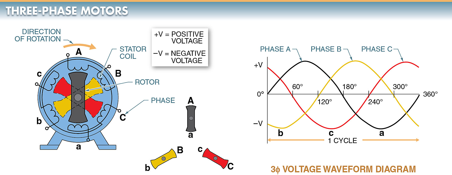
Figure 7. The coils in the stator of a three-phase motor are connected to form three separate windings (phases).
Each phase is placed in the motor so that it is 120° from the other phases. A rotating magnetic field is produced in the stator because each phase reaches its peak magnetic strength 120° away from the other phases.
Three-phase motors are self-starting and do not require an additional starting method because of the rotating magnetic field in the motor.
To develop a rotating magnetic field in a motor, the stator windings must be connected to the proper voltage level. This voltage level is determined by the manufacturer and stamped on the motor nameplate. Three-phase motors are designed as either single-voltage motors or dual-voltage motors.
TECH FACT
Three-phase motors can be used where only single-phase power exists because motor drives are available to deliver a three-phase (typically 230 VAC) output up to about 2 HP when connected to a 120 or 230 VAC single-phase power source.
Single-Voltage, Three Phase Motors
A single-voltage motor is a motor that operates at only one voltage level.
Single-voltage motors are less expensive to manufacture than dual-voltage motors, but they are limited to locations having the same voltage as the motor.
Common single-voltage, three-phase motor ratings are 230 V, 460 V, and 575 V. Other single-voltage, three-phase motor ratings are 200 V, 208 V, and 220 V.
All three-phase motors are wired so that the phases are connected together in either a wye (Y) or delta (∆) configuration.
In a single-voltage, wye-connected, three-phase motor, one end of each of the three phases is internally connected to the other phases. See Figure 8.
The remaining end of each phase is brought out externally and connected to a power line. The leads that are brought out externally are labeled terminal one (T1), terminal two (T2), and terminal three (T3).
When connected, terminals T1, T2, and T3 are matched to the three-phase power lines labeled line one (L1), line two (L2), and line three (L3).
For the motor to operate properly, the three-phase lines supplying power to the wye motor must have the same voltage and frequency as the motor.
In a single-voltage, delta-connected, three-phase motor, each winding is wired end-to-end to form a completely closed-loop circuit. See Figure 9.
At each point where the phases are connected, leads are brought out externally and labeled terminal one (T1), terminal two (T2), and terminal three (T3). These terminals, like those of a wye-connected motor, are attached to power lines one (L1), two (L2), and three (L3).
The three-phase lines supplying power to the delta motor must have the same voltage and frequency rating as the motor.
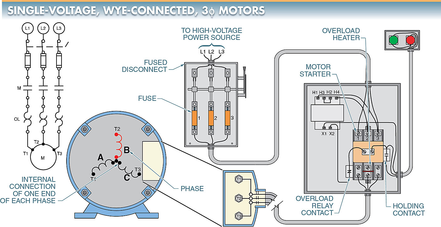
Figure 8. In a single-voltage, wye-connected, three-phase motor, one end of each phase is internally connected to the other phases.
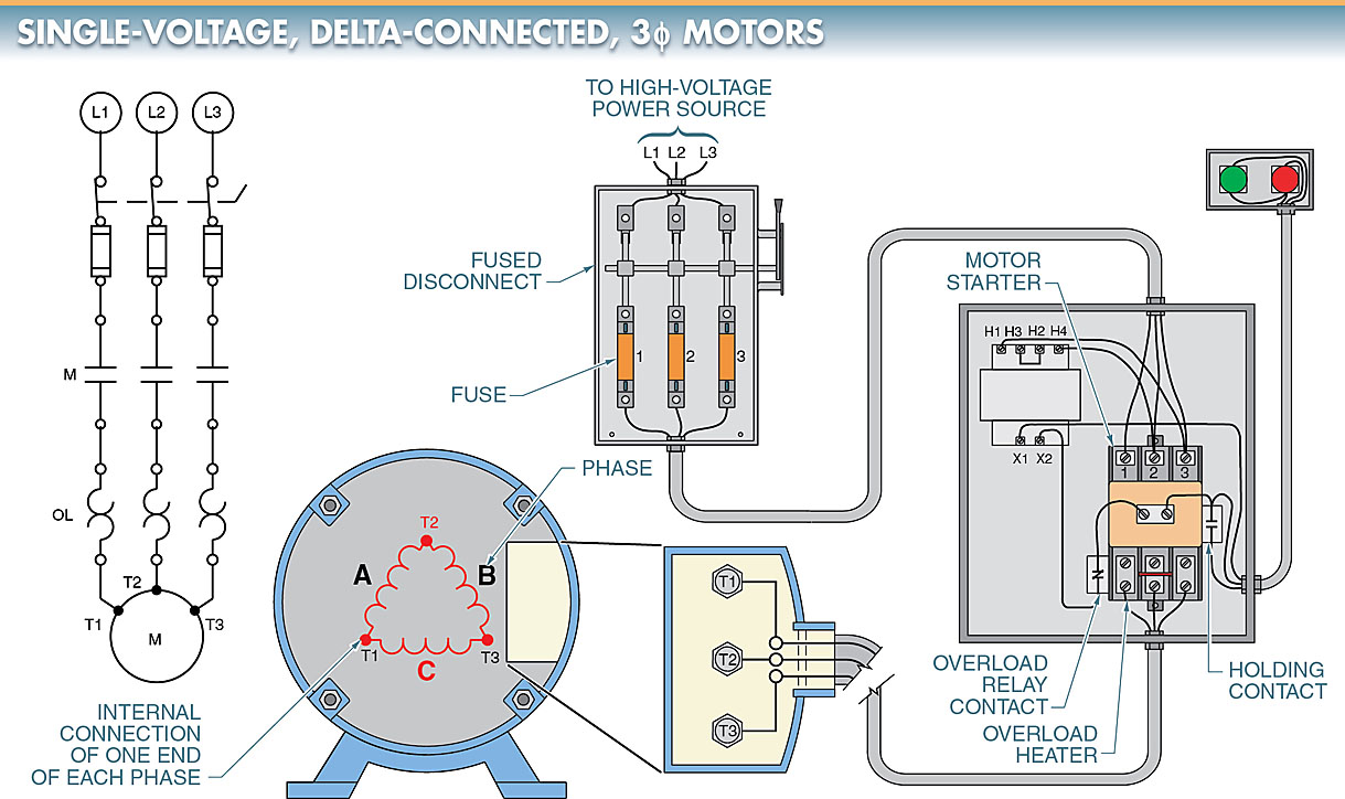
Figure 9. In a single-voltage, delta-connected, three-phase motor, each phase is wired end-to-end to form a completely closed loop.
Dual-Voltage, Three-Phase Motors
Most three-phase motors are made so that they may be connected for either of two voltages.
Making motors for two voltages enables the same motor to be used with two different power line voltages.
The normal dual-voltage rating of industrial motors is 230/460 V. The motor nameplate should be reviewed for proper voltage ratings.
The higher voltage is preferred when a choice between voltages is available. The motor uses the same amount of power and gives the same horsepower output for either high or low voltage, but as the voltage is doubled (230 V to 460 V), the current is cut in half.
Using a reduced current enables the use of a smaller wire size, which reduces the cost of installation.
Dual-voltage three-phase motors are wired so that the phases are connected in either a wye or delta configuration.
A wiring diagram is used to show the terminal numbering system for a dual-voltage, wye-connected, three-phase motor. See Figure 10.
Nine leads are brought out of the motor. These leads are marked T1 through T9 and maybe externally connected for either of the two voltages. The terminal connections for high and low voltage are normally provided on the motor nameplate.
The nine leads are connected in either series (high voltage) or parallel (low voltage). To connect a wye- connected motor for high voltage, L1 is connected to T1, L2 to T2, and L3 to T3; T4 is tied to T7, T5 to T8, and T6 to T9. This connects the individual coils in phases A, B, and C in series, each coil receiving 50% of the line-to-neutral point voltage. The neutral point equals the internal connecting point of all three phases.
To connect a wye-connected motor for low voltage, L1 is connected to T1 and T7, L2 to T2 and T8, and L3 to T3 and T9; T4 is tied to T5 and T6. This connects the individual coils in phases A, B, and C in parallel so that each coil receives 100% of the line-to-neutral point voltage.
A wiring diagram is used to show the terminal numbering system for a dual-voltage, delta- connected, and three-phase motor. See Figure 11.
The leads are marked T1 through T9 and a terminal connection chart is provided for wiring high- and low-voltage operations.
The nine leads are connected in either series or parallel for high or low voltage. In the high-voltage configuration, the coils are wired in series. In the low-voltage configuration, the coils are wired in parallel to distribute the voltage to the individual coil ratings.
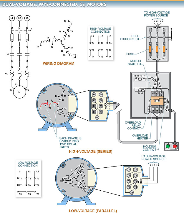
Figure 10. In a dual-voltage, wye-connected, three-phase motor, each phase coil is divided into two equal parts, and a wiring diagram is used to show the terminal numbering system.
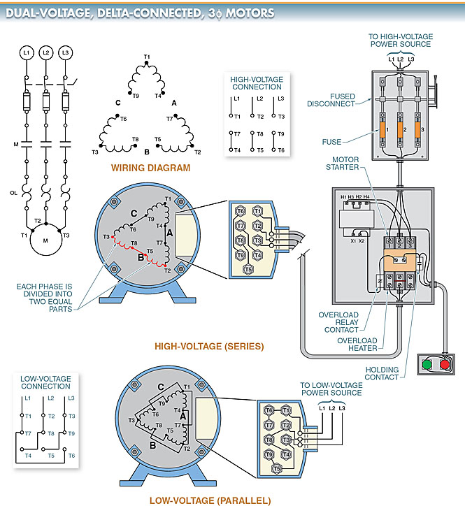
Figure 11. In a dual-voltage, delta-connected, three-phase motor, each phase coil is divided into two equal parts, and a wiring diagram is used to show the terminal numbering system.
TECH FACT
NEMA motor leads are T1, T2, and T3 where the power lines are connected. IEC motor leads are labeled U, V, and W where the power lines are connected. Likewise, NEMA power lines are labeled L1, L2, and L3, and IEC power lines are labeled R, S, and T.
AC Motor Key Takeaways
AC motor play a crucial role in a wide range of applications due to their efficiency, reliability, and adaptability. From residential appliances like refrigerators and washing machines to commercial systems such as HVAC units and elevators, these motors ensure smooth and effective operation. In industrial settings, they drive machinery, facilitate automation, and support essential processes like water pumping and material handling. Understanding the different types of AC motors, their working principles, and their applications is vital for engineers, technicians, and industry professionals.