This guide covers the stepper motor working principle (operation), specifications, switching sequence, applications, protection, and control, along with circuit diagrams.
A stepper motor is a motor that divides shaft rotation into discrete distances (steps). Unlike other motors that rotate their shafts when power is applied, stepper motors only move their shafts in small controlled increments called steps.
Stepper Motor Applications
Stepper motors are used in applications that require precise control of the position of the motor shaft. Typical applications include pen positioning, rotary and indexing table control, robotic arm movement control, laser positioning, fax machine operation, and printer control.
Stepper Motor Working Principle
The shaft of a stepper motor rotates at fixed angles when it receives an electrical pulse. The electrical pulse magnetizes the motor’s stationary field, called the stator field. The magnetic stator field moves the permanent magnet. The permanent magnet is called the rotor or armature.
The rotor steps forward to align with the stator’s magnetic field (N to S and S to N) and stops movement until another stator field is energized. See Figure 1.
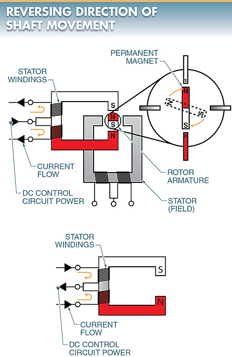
Figure 1. Stepper motors rotate at fixed angles when they receive electrical impulses.
The direction of shaft rotation is controlled by the polarity of the produced magnetic field in the stator coil.
The direction of the magnetic field determines the positive and negative side of the coil. The direction can be reversed by reversing the direction of current through the coil.
To increase the number of steps the rotor can take per 360° rotation, many individual stator and rotor segments are used. The total number of segments a motor has determined the number of individual steps the motor can take in one revolution.
Stepper motors can have 4, 8, 20, or hundreds of steps per revolution. See Figure 2.
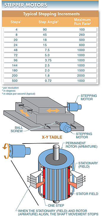
Figure 2. The total number of segments a motor has determined the number of individual steps a motor can take in one revolution.
Each input rotor pulse produces shaft rotation through the rated step angle of the stepper motor. For example, if 50 pulses are applied to a 1.8° stepper motor, the shaft rotates exactly 90° (50 × 1.8 = 90); and if 200 pulses are applied, the shaft rotates 360° (200 × 1.8 = 360).
Although stepper motors can provide precise positioning, they cannot operate large loads because their torque output is low compared to other motor types. Torque also decreases at higher operating speeds.
The operating characteristics of a stepper motor must be closely checked and compared with the operating characteristic of the application for proper operation.
Stepper Motor Specifications
They include important information on their nameplates and specification sheets. Typical stepper motor specifications include the following:
- Shaft length/diameter (2.48′′/1.5′′, etc.)
- Rated voltage (3 VDC, 12 VDC, etc.)
- Rated current (32 mA, etc.)
- Rated impedance per phase (150 Ω, 380 Ω, etc.)
- Step angle (1.5°, 2.5°, etc.)
- Torque (5 oz/in, 100 oz/in, etc.)
- Steps per revolution (24, 200, etc.)
- Noise (40 dB, etc.)
Stepper Motor Switching Sequence
Switches that turn on and off (pulse) the voltage to the coil control when the individual stator coils are energized to produce the magnetic field. The switches provide the required direct current needed to magnetize the stationary field.
The order (clockwise or counterclockwise) in which the coils are turned on and off determines the direction of rotation of the rotor and shaft of a stepper motor. The control switches do not remain on. They are turned on to move the rotor and then turned off (pulsed). See Figure 3.
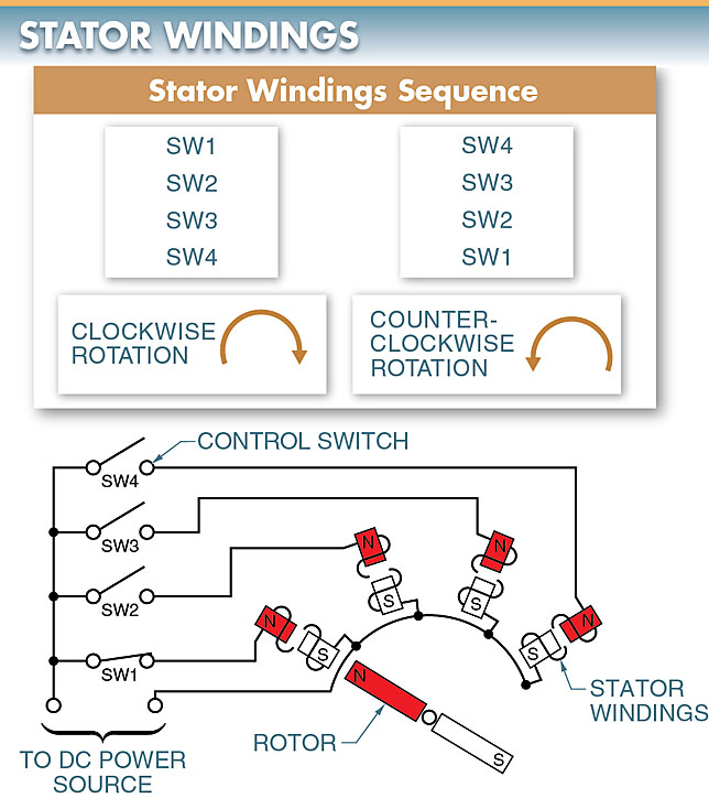
Figure 3. The order in which the stator windings are turned on and off determines the direction of rotation of the rotor and shaft of a stepper motor.
Because the stator coils are turned on and off rapidly, solid-state transistors switches are used instead of mechanical switches.
The transistor switches are controlled by an electronic control circuit that sends signals to the transistor to start or stop the flow of current through the coil.
The electronic circuit can be from a stand-alone stepper controller, a programmable logic controller (PLC), or another electronic circuit. See Figure 4.
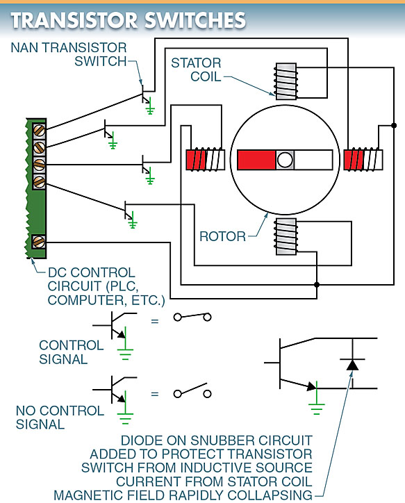
Figure 4. Transistor switches are used to rapidly turn on and off the stator coils to move the rotor.
Stepper Motor Protection
All coils produce high current (inductive surge) when their magnetic fields collapse, which can damage switch contacts. This damage can include burnt contacts in mechanical switches and component failure in electronic switches such as transistors, silicon-controlled rectifiers (SCRs), and triacs.
Transistors and SCRs are used to switch DC, and triacs are used to switch AC.
To help reduce damage, a snubber circuit is used to protect the switch. For example, a diode may be used in a DC circuit. The electronic control circuit outputs are connected so that each output performs a specific task within the system.
One stepper motor might control the x-axis and another might control the y-axis on a machine table. When using stepper motors to work together in an application, such as when controlling an x-axis and a y-axis, it is best to use the same type for both.
Stepper Motor Control
Stepper motor circuits can be open-loop or closed- loop types.
In the open-loop type, the control signals are sent to the motor and it is assumed that the motor shaft moved as required. However, the shaft may not have moved as instructed. This happens when the motor is underpowered, the load has increased above design, or there is an obstruction.
In some stepper motor applications, feedback is important since the motor may not have moved the actual steps the controller told it to. To provide feedback to the control circuit about the position of the motor shaft, an optical encoder with a disk on the motor shaft is typically used.
Stepper Motor Encoder
An encoder is a sensor (transducer) that produces discrete electrical pulses during each increment of shaft rotation. See Figure 5.
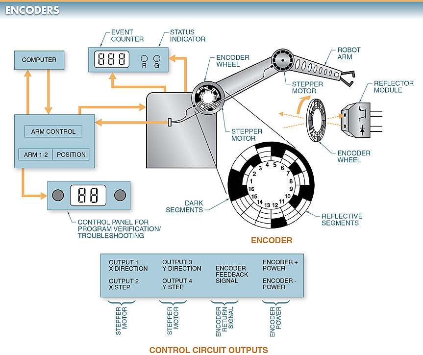
Figure 5. An encoder in Stepper Motor is used to produce discrete electrical pulses during each increment of the shaft rotation of a motor.
The encoder disk has open sections in which light beams shine through. The pulses of the light beams are sent to the electronic control circuit to compare the instructed movement to the actual movement. Any differences can be compensated for by the design of the control circuit.
Stepper Motor Key Takeaways
In conclusion, stepper motors play a crucial role in applications requiring precise control of movement and positioning. Their ability to divide shaft rotation into discrete steps makes them ideal for tasks such as robotics, CNC machines, and automated systems. Understanding their working principles, specifications, switching sequences, and control methods is essential for ensuring optimal performance and integration into various applications. Proper protection mechanisms and control strategies further enhance their reliability and longevity. As technology advances, stepper motors continue to be a fundamental component in industries requiring accuracy and repeatability.