The article provides an overview of the four main types of DC motors: DC series, DC shunt, DC compound, and DC permanent-magnet motors. It explains their internal construction, operating characteristics, torque-speed relationships, speed control methods, and common applications in various industries.
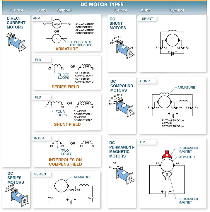
The four basic types of DC motors are DC series motors, DC shunt motors, DC compound motors, and DC permanent-magnet motors. See Figure 1. These DC motors have similar external appearances but are different in their internal construction and output performance.
Figure 1. The four basic types of DC motors Diagrams: DC series motors, DC shunt motors, DC compound motors, and DC permanent- magnet motors.
TECH FACT
DC motor armature leads are labeled A1 A2, shunt field leads are labeled F1 and F2, and series field leads are labeled S1 and S2. When DC motor leads are connected to DC power, A1, F1, and S1 are typically connected closest to the positive power side and A2, F2, and S2 are connected closest to the negative power side.
DC Series Motor
A DC series motor is a DC motor that has the series field connected in series with the armature. The field must carry the load current passing through the armature. The field has relatively few turns of heavy-gauge wire.
The wires extending from the series coil are marked S1 and S2. The wires extending from the armature are marked A1 and A2. See Figure 2.
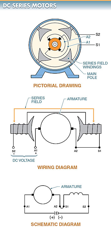
Figure 2. A DC series motor (Circuit Diagram) is a motor with the field connected in series with the armature.
DC Series Motor Characteristics
A DC series motor produces high starting torque. See Figure 3. The field coil (series field) of the motor is connected in series with the armature.
Although speed control is poor, a DC series motor produces a very high starting torque and is ideal for applications in which the starting load is large. Applications include cranes, hoists, electric buses, streetcars, railroads, and other heavy-traction applications.
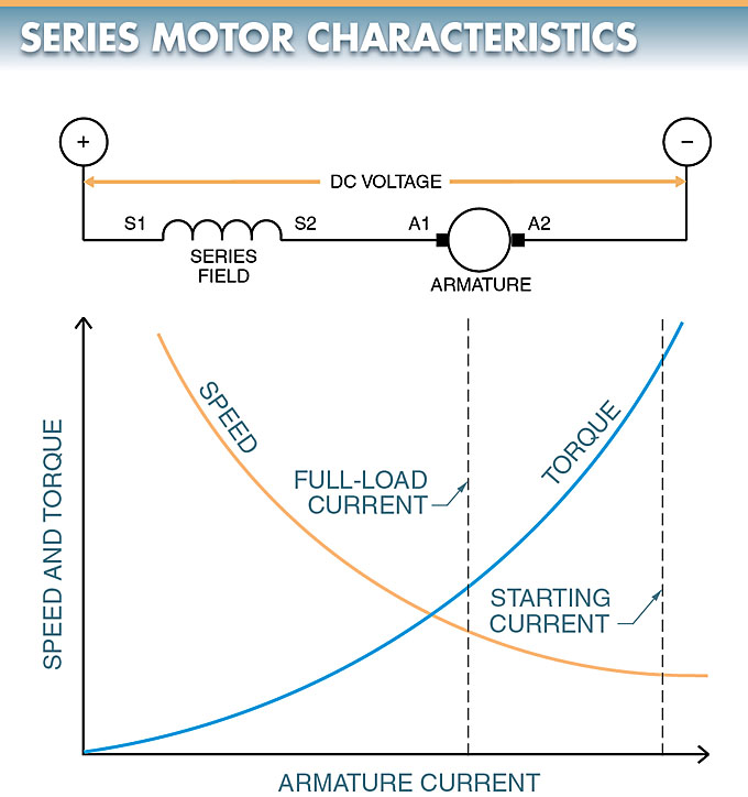
Figure 3. A DC series motor torque-speed curve
The torque that is produced by a motor depends on the strength of the magnetic field in the motor. The strength of the magnetic field depends on the amount of current that flows through the series field.
The amount of current that flows through a motor depends on the size of the load. The larger the load, the greater the current flow.
Any increase in load increases current in both the armature and series field because the armature and field are connected in series. This increased current flow is what gives a DC series motor a high torque output.
DC Series Motor torque speed Characteristics
In DC series motors, speed changes rapidly when torque changes.
When torque is high, speed is low; and when speed is high, torque is low. This occurs because there is a large flux increase as the increased current (created by the load) flows through the series field. This increased flux produces a large counter electromotive force, which greatly decreases the speed of the motor.
As the load is removed, the motor rapidly increases speed. Without a load, the motor would gain speed uncontrollably. In certain cases, the speed may become great enough to damage the motor. For this reason, a DC series motor should always be connected directly to the load and not through belts, chains, etc.
DC Series Motor Speed Control
The speed of a DC series motor is controlled by varying the applied voltage. Although the speed control of a series motor is not as good as the speed control of a shunt motor, not all applications require good speed regulation.
The advantage of a high torque output outweighs good speed control in certain applications, such as the starter motor in automobiles.
DC Shunt Motor
A DC shunt motor is a DC motor that has the field connected in shunt (parallel) with the armature.
The wires extending from the shunt field of a DC shunt motor are marked F1 and F2. The armature windings are marked A1 and A2. See Figure 4.
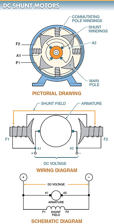
Figure 4. A DC shunt motor (Circuit Diagram) is a motor with the field connected in shunt (parallel) with the armature.
The field has numerous turns of wire, and the current in the field is independent of the armature, providing the DC shunt motor with excellent speed control.
The shunt field may be connected to the same power supply as the armature or may be connected to another power supply.
A self-excited shunt field is a shunt field connected to the same power supply as the armature. A separately excited shunt field is a shunt field connected to a different power supply than the armature.
DC Shunt Motor Applications
DC shunt motors are used where constant or adjustable speed is required and starting conditions are moderate.
Typical applications include fans, blowers, centrifugal pumps, conveyors, elevators, woodworking machinery, and metalworking machinery.
DC Shunt Motor Characteristics
In a DC shunt motor, if the voltage to the armature is reduced, the speed is also reduced. If the strength of the magnetic field is reduced, the motor speeds up.
DC shunt motors speed up with a reduction in shunt field strength because with less field strength, there is less counter electromotive force developed in the armature. When the counter electromotive force is lowered, the armature current increases, producing increased torque and speed.
To control the speed of a DC shunt motor, the voltage to the armature is varied or the shunt field current is varied. See Figure 5.
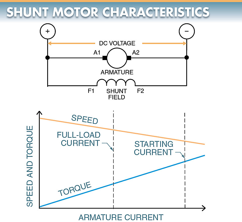
Figure 5. To control the speed of a DC shunt motor, the voltage to the armature is varied as the shunt field current is varied.
DC Shunt Motor Speed Control
A field rheostat or armature rheostat is used to adjust the speed of a DC shunt motor. See Figure 6.
The rheostat is used to increase or decrease the strength of the field or armature. Once the strength of the field is set, it remains constant regardless of changes in armature current.
As the load is increased on the armature, the armature current, and torque of the motor increase. This slows the armature, but the reduction of counter electromotive force (CEMF) simultaneously allows a further increase in armature current and thus returns the motor to the set speed. The motor runs at a fairly constant speed at any control setting.
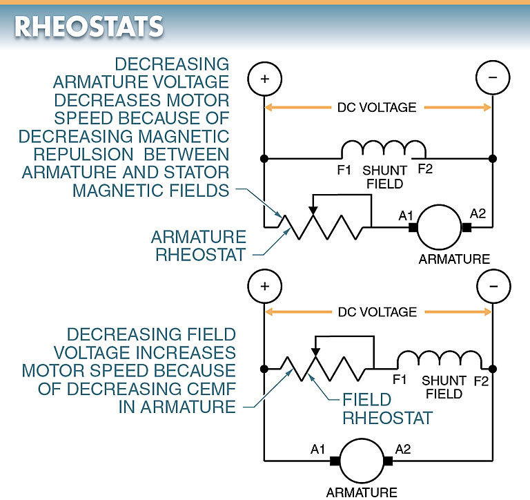
Figure 6. A field rheostat or armature rheostat is used to adjust the speed of a DC shunt motor.
DC Shunt Motor Torque-Speed Characteristics
A DC shunt motor has relatively high torque at any speed. The motor torque is directly proportional to the armature current. As armature current is increased, so is motor torque, with only a slight drop in motor speed.
DC Compound Motor
A DC compound motor is a DC motor with the field connected in both series and shunt with the armature.
The field coil is a combination of the series field (S1 and S2) and the shunt field (F1 and F2). See Figure 7.
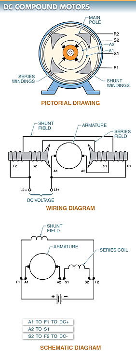
Figure 7. A DC compound motor (Circuit Diagram) is a motor with the field connected in both series and shunt with the armature.
DC Compound Motor Characteristics
The series field is connected in series with the armature. The shunt field is connected in parallel with the series field and armature combination.
This arrangement gives the motor the advantages of the DC series motor (high torque) and the DC shunt motor (constant speed). See Figure 8.
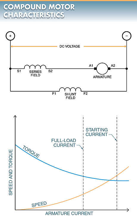
Figure 8. A DC compound motor Speed-Torque Characteristics Curve
DC Compound Motor Applications
DC compound motors are used when high starting torque and constant speed are required. Typical applications include punch presses, shears, bending machines, and hoists.
DC Compound Motor Speed Control
Speed control is obtained in a DC compound motor by changing the shunt field current strength or changing the voltage applied to the armature. This is accomplished by using a controller that uses resistors to reduce the applied voltage or by using a variable voltage supply.
DC Permanent-Magnet Motor
A DC permanent-magnet motor is a motor that uses magnets, not a winding, for the field poles.
DC permanent-magnet motors have molded magnets mounted into a steel shell. The permanent magnets are the field coils. DC power is supplied only to the armature. See Figure 9.
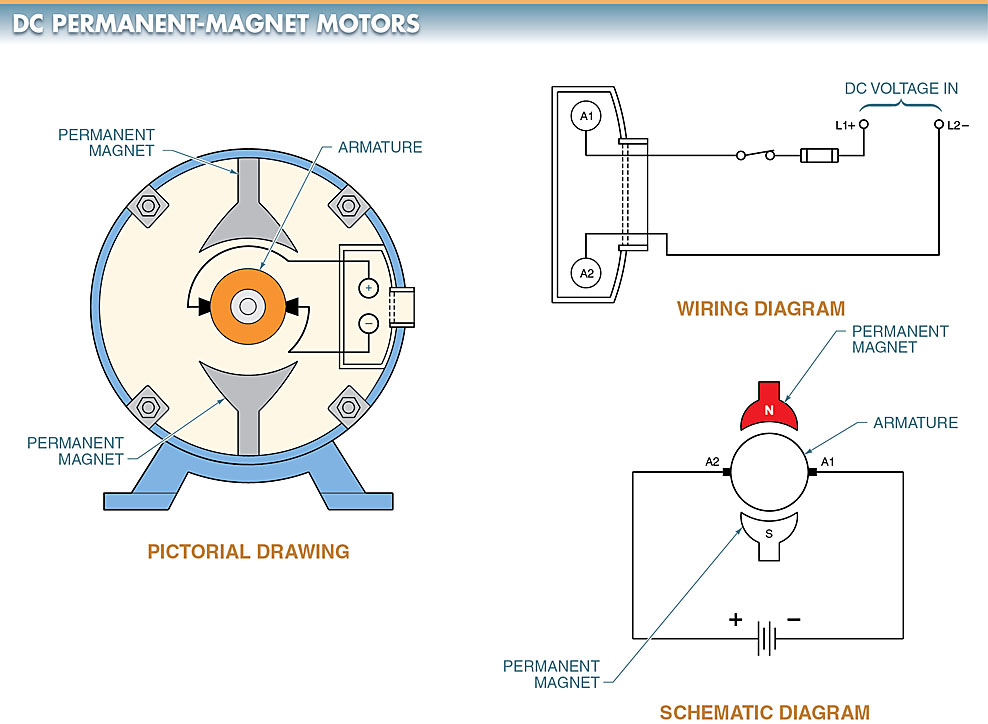
Figure 9. A DC permanent-magnet motor (Circuit Diagram) uses magnets, not a winding, for the field poles.
DC Permanent-Magnet Motor Applications
DC permanent-magnet motors are used in automobiles to control power seats, power windows, and windshield wipers.
DC Permanent-Magnet Motor Characteristics
DC permanent-magnet motors produce relatively high torque at low speeds and provide some self-braking when removed from power. Not all DC permanent-magnet motors are designed to run continuously because they overheat rapidly. Overheating destroys the permanent magnets.
Types DC Motors Key Takeaways
In conclusion, understanding the four main types of DC motors: DC series, DC shunt, DC compound, and DC permanent-magnet motors—is crucial for selecting the right motor for various industrial and commercial applications. Each type offers unique advantages, such as high starting torque in DC series motors, precise speed control in DC shunt motors, a balance of torque and speed stability in DC compound motors, and compact efficiency in DC permanent-magnet motors. These motors play a vital role in applications ranging from transportation and manufacturing to automation and consumer electronics.