The article discusses various types of solid state relay (SSR) switching methods—zero switching, instant-on, peak switching, and analog switching—each suited for controlling different electrical loads. It outlines their operational characteristics and typical applications in electrical systems.
The solid state relay used in an application depends on the load to be controlled. The different SSRs are designed to properly control certain loads. The four basic solid state relays are the zero switching (ZS) relay, instant-on (IO) relay, peak switching (PS) relay, and analog switching (AS) relay.
Zero Switching
A zero-switching relay is a solid state relay that turns on the load when the control voltage is applied and the voltage at the load crosses zero (or within a few volts of zero).
The relay turns off the load when the control voltage is removed and the current in the load crosses zero. See Figure 1.
The zero-switching relay is the most widely used relay. Zero switching relays are designed to control resistive loads. Zero switching relays control the temperature of heating elements, soldering irons, extruders for forming plastic, incubators, and ovens. Zero switching relays control the switching of incandescent lamps, tungsten lamps, flashing lamps, and programmable controller interfacing.
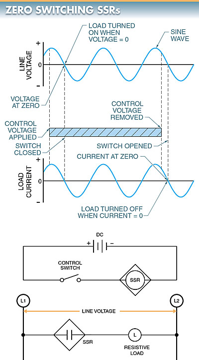
Figure 1. A zero-switching relay turns on the load when the control voltage is applied and the voltage at the load crosses zero.
Instant-On Switching
An instant-on switching relay is a solid state relay that turns on the load immediately when the control voltage is present. This allows the load to be turned on at any point on the AC sine wave.
The relay turns off when the control voltage is removed and the current in the load crosses zero. Instant-on switching is exactly like electromechanical switching because both switching methods turn on the load at any point on the AC sine wave. See Figure 2.
Instant-on relays are designed to control inductive loads. In inductive loads, voltage and current are not in phase and the loads turn on at a point other than the zero voltage point that is preferred.
Instant-on relays control the switching of contactors, magnetic valves and starters, valve position controls, magnetic brakes, small motors (used for position control), 1φ motors, small 3φ motors, lighting systems, programmable controller interfaces, and phase controls.
Peak Switching
A peak switching relay is a solid state relay that turns on the load when the control voltage is present and the voltage at the load is at its peak.
The relay turns off when the control voltage is removed and the current in the load crosses zero. Peak switching is preferred when the voltage and current are about 2° out of phase because switching at peak voltage is switching at close to zero current. See Figure 3.
Peak switching relays control transformers and other heavy inductive loads and limit the current in the first half period of the AC sine wave.
Peak switching relays control the switching of transformers, large motors, DC loads, high inductive lamps, magnetic valves, and small DC motors.
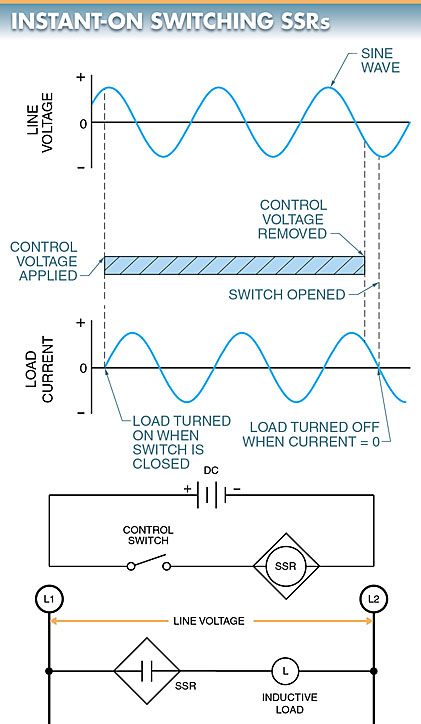
Figure 2. An instant-on switching relay turns on the load immediately when the control voltage is present.

Figure 3. A peak switching relay turns on the load when the control voltage is present and the voltage at the load is at its peak.
Analog Switching
An analog switching relay is a solid state relay that has an infinite number of possible output voltages within the rated range of the relay.
An analog switching relay has a built-in synchronizing circuit that controls the amount of output voltage as a function of the input voltage. This allows for a ramp-up function of the load. In a ramp-up function, the voltage at the load starts at a low level and is increased over a period of time. The relay turns off when the control voltage is removed and the current in the load crosses zero. See Figure 4.
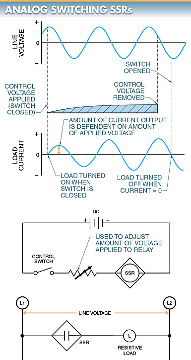
Figure 4. An analog switching relay has an infinite number of possible output voltages within the rated range of the relay.
A typical analog switching relay has an input control voltage of 0 VDC to 5 VDC. These low and high limits correspond respectively to no switching and full switching on the output load.
For any voltage between 0 VDC and 5 VDC, the output is a percentage of the available output voltage. However, the output is normally nonlinear when compared to the input. Also, the manufacturer’s data must be checked.
Analog switching relays are designed for closed-loop applications. One closed-loop application is a temperature control with feedback from a temperature sensor to the controller.
In a closed-loop system, the amount of output is directly proportional to the amount of the input signal. For example, if there is a small temperature difference between the actual temperature and the set temperature, the load (heating element) is given low power. However, if there is a large temperature difference between the actual temperature and the set temperature, the load (heating element) is given high power. This relay may also be used for starting high-power incandescent lamps to reduce the inrush current.
Solid State Relay Switching Methods Key Takeaways
Understanding the different solid state relay switching methods is essential for selecting the right relay based on the specific load requirements in various applications. Each type—zero switching, instant-on, peak switching, and analog switching—offers unique advantages that enhance efficiency, protect equipment, and optimize performance in both industrial and commercial electrical systems.