The article provides an overview of solid-state relay (SSR) components and circuit configurations, explaining how SSRs function electronically without moving parts. It discusses key elements such as input, control, and output circuits, and outlines various applications and configurations including two-wire, three-wire, transistor control, and series/parallel connections.
A relay is a device that controls one electrical circuit by opening and closing another circuit. A small voltage applied to relay results in a larger voltage being switched. A solid-state relay (SSR) is a switching device that has no contacts and switches entirely by electronic means.
An SSR uses a silicon-controlled rectifier (SCR), triac, or transistor output instead of mechanical contacts to switch the controlled power. The output is optically coupled to a light-emitting diode (LED) light source inside the relay. The relay is turned on when the LED is energized, usually with low-voltage DC power. See Figure 1.
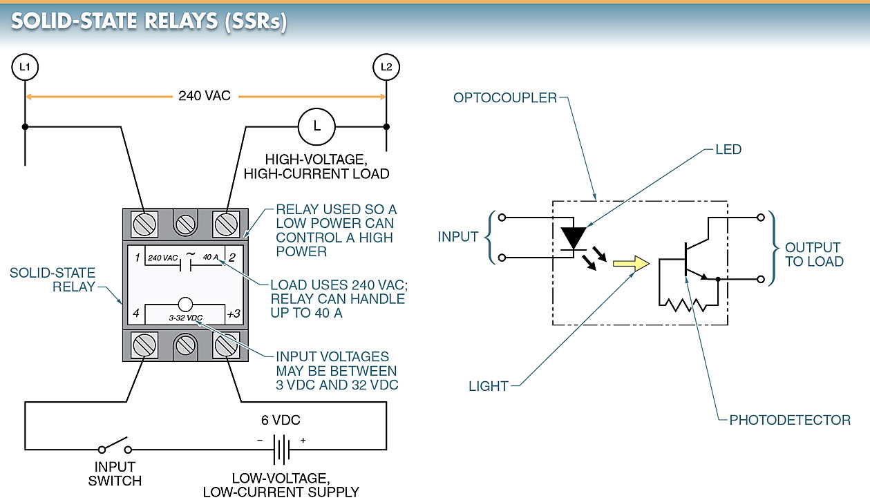
Figure 1. A solid-state relay (SSR) is an electronic switching device that has no moving parts.
The industrial control market has moved to solid-state electronics. Due to declining cost, high reliability, and immense capability, solid-state devices are replacing many devices that operate on mechanical and electrical principles.
The selection of a solid-state relay is based on the electrical, mechanical, and cost characteristics of each device and the required application.
Solid State Relay Circuit
A solid state relay circuit consists of an input circuit, a control circuit, and an output (load-switching) circuit. These circuits may be used in any combination to provide many different solid-state switching applications. See Figure 2.
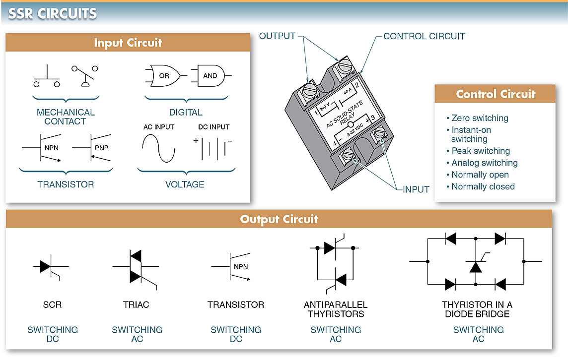
Figure 2. A solid state relay circuit consists of an input circuit, a control circuit, and an output (load-switching) circuit.
1. Input Circuit
An input circuit is the part of an SSR to which the control component is connected. The input circuit performs the same function as the coil of an EMR.
The input circuit is activated by applying a voltage to the input of the relay that is higher than the specified pickup voltage of the relay. The input circuit is deactivated when a voltage less than the specified minimum dropout voltage of the relay is applied.
Some SSRs have a fixed input voltage rating, such as 12 VDC. Most SSRs have an input voltage range, such as 3 VDC to 32 VDC. The voltage range allows a single SSR to be used with most electronic circuits.
The input voltage of a solid state relay may be controlled (switched) through mechanical contacts, transistors, digital gates, etc. Most SSRs may be switched directly by low-power devices, which include integrated circuits, without adding external buffers or current-limiting devices. Variable-input devices, such as thermistors, may also be used to switch the input voltage of an SSR.
2. Control Circuits
A control circuit is the part of a solid state relay that determines when the output component is energized or de-energized.
The control circuit functions as the interface between the input and output circuits. In a solid state relay, the interface is accomplished by electronic circuitry inside the SSR. In an EMR, the interface is accomplished by a magnetic coil that closes a set of mechanical contacts.
When the control circuit receives the input voltage, the circuit is switched or not switched depending on whether the relay is a zero switching, instant-on, peak switching, or analog switching relay.
Each relay is designed to turn on the load-switching circuit at a predetermined voltage point. For example, a zero-switching relay allows the load to be turned on only after the voltage across the load is at or near zero. The zero-switching function provides a number of benefits, such as the elimination of high inrush currents on the load.
3. Output (Load-Switching) Circuits
The output (load- switching) circuit of a solid state relay is the load switched by the SSR. The output circuit performs the same function as the mechanical contacts of an electromechanical relay. However, unlike the multiple output contacts of EMRs, SSRs normally have only one output contact.
Most solid state relays use a thyristor as the output switching component. Thyristors change from the OFF state (contacts open) to the ON state (contacts closed) very quickly when their gate switches on. This fast switching action allows for high-speed switching of loads.
The output switching device used depends on the type of load to be controlled. Different outputs are required when switching DC circuits than are required when switching AC circuits.
Common output switching devices used in SSRs include the following:
- SCRs are used to switch high-current DC loads.
- Triacs are used to switch low-current AC loads.
- Transistors are used to switch low-current DC loads.
- Anti-parallel Thyristors are used to switch high- current AC loads. They are able to dissipate more heat than a triac.
- Thyristors in diode bridges are used to switch low- current AC loads.
Solid State Relay Circuit Capabilities
A solid state relay can be used to control most of the same circuits that an EMR is used to control. Because an SSR differs from an EMR in function, the control circuit for an SSR differs from that of an EMR. This difference is how the relay is connected to the circuit. An SSR performs the same circuit functions as an EMR but with a slightly different control circuit.
- Two-Wire Control
A solid state relay may be used to control a load using a momentary control such as a pushbutton. See Figure 3. In this circuit, a push button signals the SSR, which turns on the load.
The pushbutton must be held down to keep the load turned on. The load is turned off when the pushbutton is released. This circuit is identical in operation to the standard two-wire control circuit used with EMRs, magnetic motor starters, and contactors. For this reason, the pushbutton could be changed to any manual, mechanical, or automatic control device for simple ON/OFF operation.
The same circuit may be used for liquid level control if the pushbutton is replaced with a float switch.
- Three-Wire Memory Control
A solid state relay may be used with an SCR to latch a load in the ON condition. See Figure 4. This circuit is identical in operation to the standard three-wire memory control circuit.
An SCR is used to add memory after the start pushbutton is pressed. An SCR acts as a current-operated OFF-to-ON switch.
The SCR does not allow the DC control current to pass through until a current is applied to its gate. There must be a flow of a definite minimum current to turn on the SCR. This is accomplished when the start pushbutton is pressed.
Once the gate of the SCR has voltage applied, the SCR is latched in the ON condition and allows the DC control voltage to pass through even after the start pushbutton is released.
Resistor R1 is used as a current-limiting resistor for the gate and is determined by gate current and supply voltage.
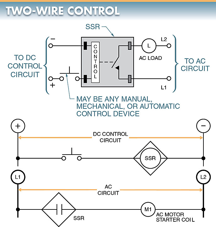
Figure 3. A solid state relay may be used to control a load using a momentary control such as a pushbutton.
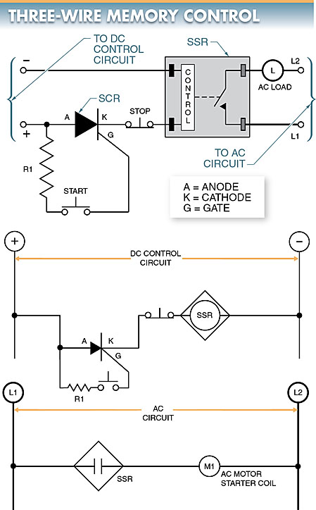
Figure 4. A solid state relay may be used with an SCR to latch a load in the ON condition.
Tech Fact
When a motor drive is programmed, the control circuit must be programmed for two-wire or three-wire operation.
The term “two- wire” means that a switch can perform two functions. The term “three-wire” means that a switch can perform only one function. All three-wire switches require a second switch to control the load.
Equivalent NC Contacts
A solid state relay may be used to simulate an equivalent normally closed (NC) contact condition. An NC contact must be electrically made because most SSRs have the equivalent of a normally open (NO) contact. This is accomplished by allowing the DC control voltage to be connected to the SSR through a current-limiting resistor (R). See Figure 5.
The load is held in the ON condition because the control voltage is present on the SSR. The selector switch is moved to turn off the load. This allows the DC control voltage to take the path of least resistance and electrically remove the control voltage from the relay. This also turns off the load until the pushbutton is released.
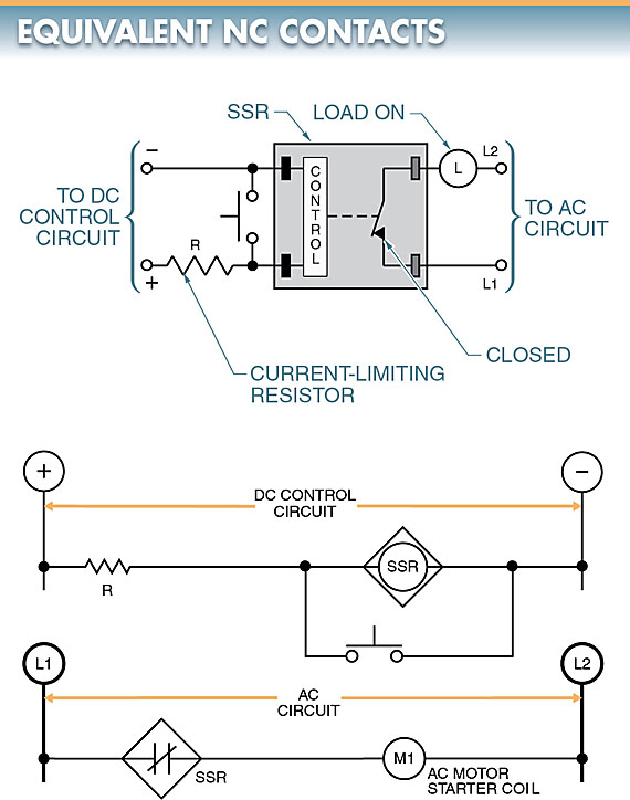
Figure 5. A solid state relay with a current-limiting resistor may be used to simulate an equivalent normally closed (NC) contact condition.
Transistor Control
Solid state relays are also capable of being controlled by electronic control signals from logic gates and transistors. See Figure 6.
In this circuit, the SSR is controlled through an NPN transistor that receives its signal from IC logic gates, etc. Two resistors (R1 and R2) are used as current-limiting resistors.
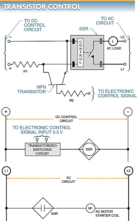
Figure 6. SSRs may be controlled by electronic control signals from logic gates and transistors
Series and Parallel Control
Solid state relays can be connected in series or parallel to create multi-contacts that are controlled by one input device. Multi-contact SSRs may also be used.
Three SSR control inputs may be connected in parallel so that when the switch is closed, all three are actuated. See Figure 7. This controls the 3φ circuit.
In this application, the DC control voltage across each SSR is equal to the DC supply voltage because they are connected in parallel. When a multi-contact SSR is used, there is only one input that controls all output switches.
SSRs can be connected in series to control a 3φ circuit. See Figure 8. The DC supply voltage is divided across the three SSRs when the switch is closed. For this reason, the DC supply voltage must be at least three times the minimum operating voltage of each relay.
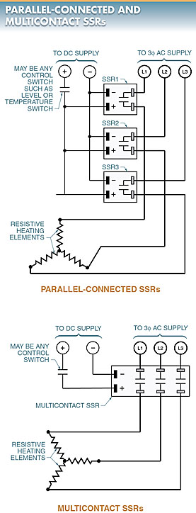
Figure 7. Three solid state relays may be connected in parallel to control a 3φ circuit or a multi-contact SSR may be used.
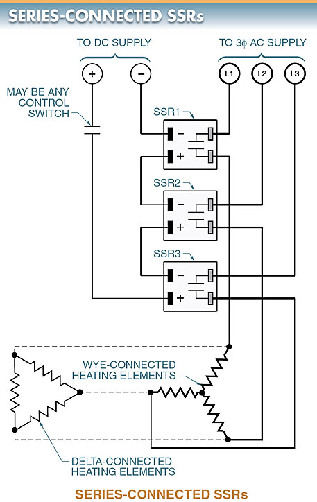
Figure 8. Three solid state relays may be connected in series to control a 3φ circuit. When SSRs are connected in series, the DC supply must be three times the minimum operating voltage of each relay.
Solid-State Relay Circuit Components Key Takeaways
Understanding solid-state relays (SSRs), their internal components, and various circuit configurations is essential for effectively leveraging their capabilities in modern electronic control systems. These relays offer critical advantages—such as fast switching, high reliability, and compatibility with low-voltage control signals—making them ideal for a wide range of applications including industrial automation, motor control, and electronic switching. By exploring configurations like two-wire, three-wire memory, transistor control, and series/parallel arrangements, engineers can tailor SSR use to specific operational requirements.