Temperature rise is the largest problem in applications that use solid state relay (SSR). As temperature increases, the failure rate of SSRs increases. As temperature increases, the number of operations of an SSR decreases. The higher the heat in an SSR, the more problems occur. See Figure 1.
The failure rate of most solid state relays doubles for every 10°C temperature rise above an ambient temperature of 40°C. An ambient temperature of 40°C is considered standard by most manufacturers.
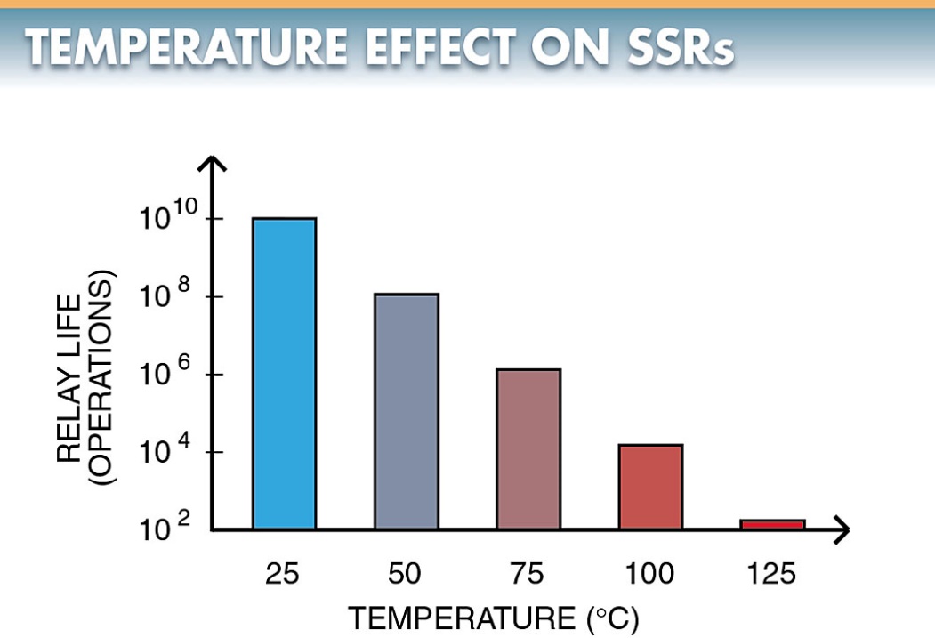
Figure 1. As temperature increases, the number of operations of a solid-state relays decreases.
Solid-state relay manufacturers specify the maximum relay temperature permitted. The relay must be properly cooled to ensure that the temperature does not exceed the specified maximum safe value.
Proper cooling is accomplished by installing the solid state relay to the correct heat sink. A heat sink is chosen based on the maximum amount of load current controlled.
Heat Sinks
The performance of a solid state relay is affected by ambient temperature. The ambient temperature of a relay is a combination of the temperature of the relay location and the type of enclosure used.
The temperature inside an enclosure may be much higher than the ambient temperature of an enclosure that allows good air flow.
The temperature inside an enclosure increases if the enclosure is located next to a heat source or in the sun. The electronic circuit and solid state relay also produce heat. Forced-air cooling is required in some applications.
- You May Also Read: Solid State Timers
Tech Fact
Higher-than-rated heat is a common cause of SSR failures. High heat is difficult to locate and measure.
To determine if the solid state relay is overheated, the relay is operated at full load for at least one hour. An IR (infrared) noncontact temperature test instrument or thermal imager is used to measure the heat on the relay.
The heat should be no more than 75% of the relay’s maximum heat rating. A thermal imager works best because it can visually indicate the exact location of heat on the relay, heat sink, and the surrounding area.
Selecting Heat Sinks
A low resistance to heat flow is required to remove the heat produced by an SSR. The opposition to heat flow is thermal resistance.
Thermal resistance (RTH) is the ability of a device to impede the flow of heat. Thermal resistance is a function of the surface area of a heat sink and the conduction coefficient of the heat sink material. Thermal resistance (RTH) is expressed in degrees Celsius per watt (°C/W).
Heat sink manufacturers list the thermal resistance of heat sinks. The lower the thermal resistance value, the more easily the heat sink dissipates heat. The larger the thermal resistance value, the less effectively the heat sink dissipates heat.
The thermal resistance value of a heat sink is used with a solid state relay load current/ambient temperature chart to determine the size of the heat sink required. See Figure 2.
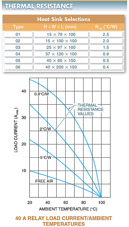
Figure 2. The thermal resistance value of a heat sink is used with an SSR load current/ambient temperature chart to determine the size of the heat sink required.
A relay can control a large amount of current when a heat sink with a low thermal resistance number is used. A relay can control the least amount of current when no heat sink (free-air mounting) is used. Heat conduction through a relay and into a heat sink can be maximized with the following recommendations:
- Use heat sinks made of a material that has a high thermal conductivity. Silver has the highest thermal conductivity rating. Copper has the highest practical thermal conductivity rating. Aluminum has a good thermal conductivity rating and is the most cost-effective and widely used heat sink.
- Keep the thermal path as short as possible.
- Use the largest cross-sectional surface area in the smallest space.
- Always use thermal grease or pads between the relay housing and the heat sink to eliminate air gaps and aid in thermal conductivity.
Mounting Heat Sinks
A heat sink must be correctly mounted to ensure proper heat transfer. A heat sink can be properly mounted using the following recommendations:
- Choose a smooth mounting surface. The surfaces between a heat sink and a solid-state device should be as flat and smooth as possible. Ensure that the mounting bolts and screws are securely tightened.
- Locate heat-producing devices so that the temperature is spread over a large area. This helps prevent higher temperature areas.
- Use heat sinks with fins to achieve as large a surface area as possible.
- Ensure that the heat from one heat sink does not add to the heat from another heat sink.
- Always use thermal grease between the heat sink and the solid-state device to ensure maximum heat transfer.
Relay Current Problems
The overcurrent passing through a solid state relay must be kept below the maximum load current rating of the relay. An overload protection fuse is used to prevent overcurrents from damaging a solid state relay.
An overload protection fuse opens the circuit when the current is increased to a higher value than the nominal load current. The fuse should be an instantaneous fuse used for the protection of semiconductors. See Figure 3.
Relay Voltage Problems
Most AC power lines contain voltage spikes superimposed on the voltage sine wave. Voltage spikes are produced by the switching of motors, solenoids, transformers, motor starters, contactors, and other inductive loads. Large spikes are also produced when lightning strikes the power distribution system.
The output element of a relay can exceed its breakdown voltage and turn on for part of a half period if overvoltage protection is not provided. This short turn-on can cause problems in the circuit.
Varistors are added to the relay output terminals to prevent an overvoltage problem. A varistor should be rated 10% higher than the line voltage of the output circuit. The varistor bypasses the transient current. See Figure 4.
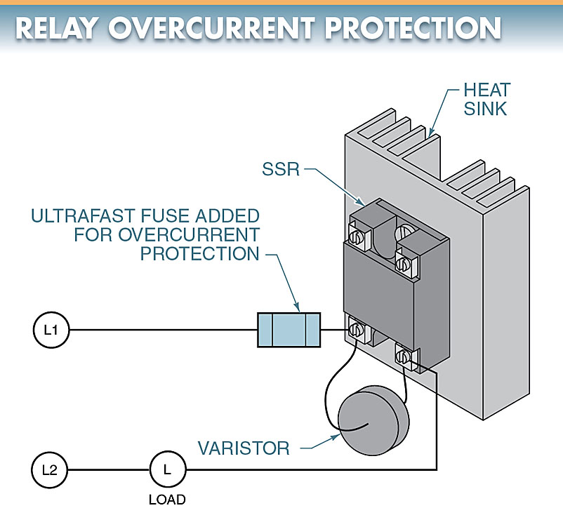
Figure 3. An overload protection fuse opens the circuit when the current is increased to a higher value than the nominal load current.
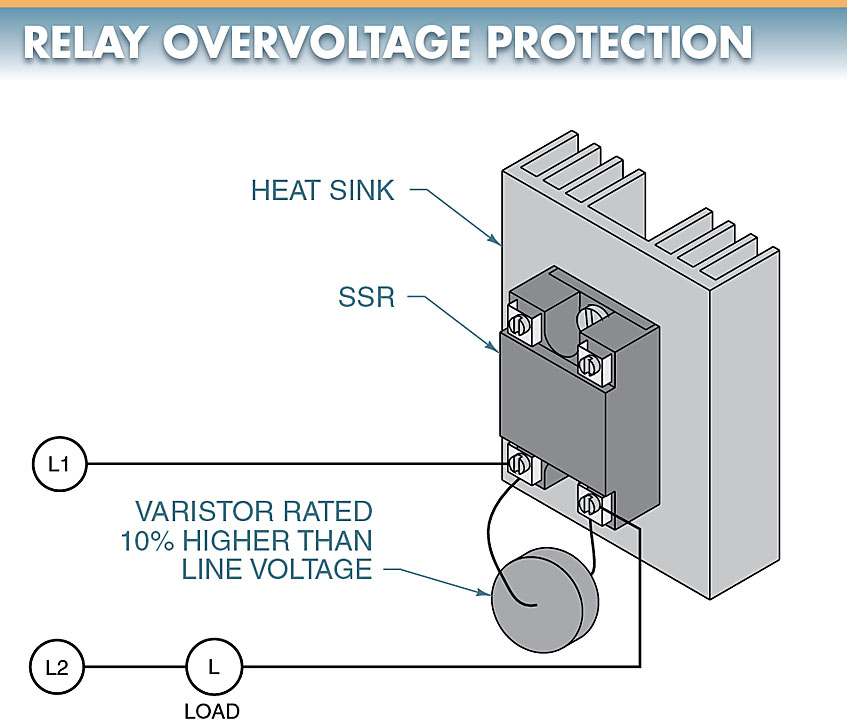
Figure 4. Varistors are added to relay output terminals to prevent an overvoltage problem.
Voltage Drop
In all series circuits, the total circuit voltage is dropped across the circuit components. The higher the resistance of any component, the higher the voltage drop. The lower the resistance of any component, the lower the voltage drop. Thus, an open switch that has a meter connected across it shows a very high voltage drop because the meter and open switch have very high resistance when compared to the load.
Conversely, a closed switch that has a meter connected across it shows a very low voltage drop because the meter is closed and closed switches have very low resistance when compared to the load.
A voltage drop in the switching component is unavoidable in a solid state relay. The voltage drop produces heat. The larger the current passing through the relay, the greater the amount of heat produced. The generated heat affects relay operation and can destroy the relay if it is not removed. See Figure 5.
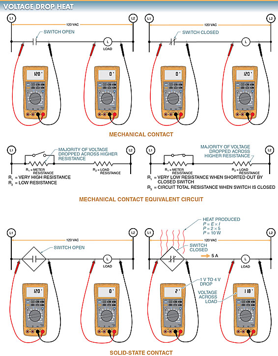
Figure 5. The voltage drop in the switching component of an SSR produces heat and can destroy the relay if it is not removed.
The voltage drop in an SSR is usually 1 V to 1.6 V, depending on the load current. For small loads (less than 1 A), the heat produced is safely dissipated through the relay’s case. High-current loads require a heat sink to dissipate the extra heat. See Figure 6.
For example, if the load current in a circuit is 1 A and the SSR switching device has a 2 V drop, the power generated is 2 W. The 2 W of power generates heat that can be dissipated through the relay’s case.
However, if the load current in a circuit is 20 A and the SSR switching device has a 2 V drop, the power generated in the device is 40 W. The 40 W of power generates heat that requires a heat sink to safely dissipate the heat.
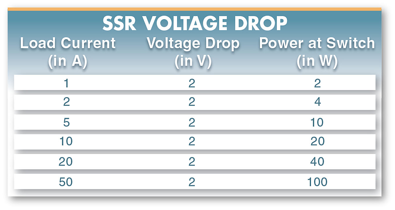
Figure 6. For small loads (less than 1 A), the heat produced in a solid state relay is safely dissipated through the relay’s case.

