The article provides an overview of series circuit, explaining their structure, behavior of current and voltage, and the role of resistors connected in series. It also introduces key concepts like Ohm’s Law, Kirchhoff’s Voltage Law, voltage drop ratios, and practical examples for calculating current and voltage in series circuits.
Series Circuit Definition
A series circuit can be identified by the connection between components or by the current through them. For example, in the circuit of Figure 1, R1 and R2 are connected in series because no other component or branch is connected to the junction of R1 and R2. None of the junctions in this circuit have a second branch, so all of the components are in series. Thus, a series circuit has only one path for current.
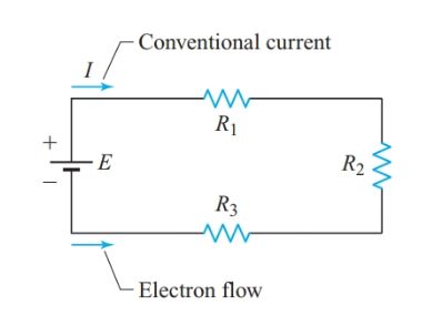
Figure 1 Simple series circuit
Since resistors cannot store charge, the flow of electrons into R1 is equal to the flow of electrons out of R1, which in turn is equal to the flow of electrons into R2.
Similarly, the flow of electrons through the source is equal to the flow of electrons through any other part of the series circuit. Georg Ohm was the first person to recognize this key property of series circuits.
The current is the same in all parts of a simple series circuit. Conversely, two or more electric components are in series if a common current flows through them.
Since the current in a series circuit is common to all components, it is not necessary to use a subscript with I to distinguish the current through the various components.
In the circuit of Figure 1, I represents the current through R1, R2, and R3, as well as the current through the source and the connecting wires.
Suppose that resistor R1 is made with 2 m of Nichrome wire, while resistor R2 contains 1 m and R3 contains 3 m of the same wire.
An electron flowing through the circuit passes through a total of 6 m of Nichrome wire. Since the resistance of an electric conductor is directly proportional to its length, the total resistance of this circuit is the sum of the individual resistances. Generalizing,
The total resistance of a series circuit equals the sum of all the individual resistances in the circuit:
$\begin{matrix} {{R}_{T}}={{R}_{1}}+{{R}_{2}}+{{R}_{3}}+\cdots & {} & \left( 1 \right) \\\end{matrix}$
Once we know the total resistance of a series circuit, we can use Ohm’s law to find the common current:
\[I=\frac{E}{{{R}_{T}}}\]
This current produces a total voltage drop VT, equal to the applied voltage E. Since the current through all the resistors is equal, the voltage drops across equal resistances are also equal.
Series Circuit Example 1
What current will flow in a series circuit consisting of a 45-Ω source, a 20- Ω, a 10- Ω, and a 30- Ω resistor?
Solution
\[\begin{align} & {{R}_{T}}={{R}_{1}}+{{R}_{2}}+{{R}_{3}}=20+10+30=60\Omega \\ & I=\frac{E}{{{R}_{T}}}=\frac{45V}{60\Omega }=0.75A \\\end{align}\]
The current drawn from the source is exactly the same for a single 60-V resistor connected to its terminals as for the 20-V, 10-V, and 30-V resistors connected in series. Therefore, we can think of the resistances in series as being replaced by a single equivalent resistance Req.
Figure 2 shows the equivalent circuit for the series circuit in Figure 1. When we analyze more elaborate circuits, we simplify a circuit by replacing two or more components in series with a single equivalent component.
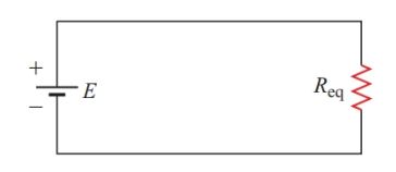
Figure 2 Equivalent circuit of Figure 1
Voltage Drops in Series Circuits
Figure 3 shows the simple series circuit of Figure 1 with a voltmeter and an ammeter added. Although the positions of R1 and R3 have changed in the circuit diagram, the connections between the components are the same as in Figure 1.
The ammeter must be connected in series with the circuit in order to measure the current through it.
Since the voltmeter is connected between points B and C, it measures the potential difference across R2. The ideal voltmeter draws negligible current and thus does affect the behavior of the circuit.
In the circuit of Figure 3, electrons experience a potential rise inside the voltage source as it uses energy to move them from the positive terminal to the negative terminal.
As electrons flow around the external circuit, they lose the potential energy they gained while moving through the source. Hence, the electrons at point D are at a higher potential than those at point C, and electrons at point B are at a higher potential than those at point A.
Similarly, electrons at point B are at a lower potential than those at point C, and so on.
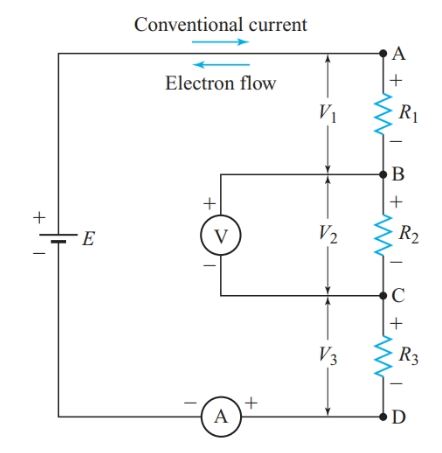
Figure 3 Polarity of voltage drops in a series circuit
If negative ions in the voltage source are free to move, they flow in the same direction as the electrons. Any positive charge carriers flow in the opposite direction. Positive charge carriers inside a voltage source experience a potential rise as they move from the negative to the positive terminal.
A voltage source is an active circuit element since it generates electric energy (at the expense of some other form of energy). Passive circuit elements consume electric energy.
Electrons flow from the negative terminal to the positive terminal of a passive component. Thus, the polarity of the voltage drops indicates the direction of current flows in these components.
Note that an ammeter is a passive circuit element. Electrons enter the ammeter through its negative terminal and leave through its positive terminal.
In the circuit of Figure 3, electrons flow counterclockwise around the circuit. We can, therefore, mark the polarities of all voltage drops with 2 and 1 signs. The end of the resistor at which electrons enter is marked 2 and the end of the resistor from which electrons leave is marked 1.
In the circuit of Figure 3, the positive end of R3 is connected to the negative end of R2, and so on. So, point C is positive with respect to point D, and point B is even more positive with respect to point D. Similarly, point C is negative with respect to point A, and so on.
For circuit diagrams, the nature of the actual charge carriers is not particularly important, but we often need to keep track of current direction. The direction of both conventional current and electron flow are shown in Figure 3.
The polarities of the voltage drops are exactly the same using either approach, but conventional current “flows” from the positive terminal of a passive circuit element to its negative terminal.
The remainder of the text will show only the direction of conventional current unless the nature of the actual charge carriers is important.
Double-Subscript Notation
In Figure 3, V1 represents the voltage drop across R1. The polarity of V1 is obvious since terminal A is positive with respect to terminal B.
Double-subscript notation lets us indicate the polarity of voltage drops. For example, VAB represents the potential at point A with respect to point B. The second subscript normally designates the reference point. In Figure 3, VAB is a positive voltage, VBA is negative, and VAB=-VBA.
The double-subscript notation is essential for keeping track of voltage polarities and current directions in three-phase circuits. For most of the dc circuits, the single-subscript notation is adequate.
Kirchhoff’s Voltage Law
Multiplying both sides of Equation 1 by I gives
$I{{R}_{T}}=I{{R}_{1}}+I{{R}_{2}}+I{{R}_{3}}+\cdots $
Since
$\begin{matrix} E=I{{R}_{T}} & and & V=IR \\\end{matrix}$
Hence,
$E\begin{matrix} ={{V}_{1}}+{{V}_{2}}+{{V}_{3}}+\cdots & {} & \left( 2 \right) \\\end{matrix}$
In a series circuit, the sum of all the voltage drops across the individual resistances equals the applied voltage.
The German physicist Gustav Robert Kirchhoff (1824–1887) discovered that a similar relationship applies to any complete electric circuit.
Kirchhoff’s voltage law: In any complete electric circuit, the algebraic sum of applied voltages equals the algebraic sum of the voltage drops.
Kirchhoff’s voltage law provides us with another method for solving Example 1.
Series Circuit Example 1A
What current will flow in a series circuit consisting of a 45-V source, a 20-V, a 10-V, and a 30-V resistor?
Solution
$\begin{align} & E=I{{R}_{1}}+I{{R}_{2}}+I{{R}_{3}} \\ & 45=20I+10I+30I=60I \\ & I=\frac{45V}{60\Omega }=0.75A \\\end{align}$
Characteristics of Series Circuits
Since the current is the same through all components of a series circuit, applying Ohm’s law to the voltage drops gives
\[I=\frac{{{V}_{1}}}{{{R}_{1}}}=\frac{{{V}_{2}}}{{{R}_{2}}}=\frac{{{V}_{3}}}{{{R}_{3}}}=\frac{{{V}_{T}}}{{{R}_{T}}}\]
By transposing variables in each pair of equal terms, we get
\[\begin{matrix} \begin{matrix} \frac{{{V}_{1}}}{{{V}_{2}}}=\frac{{{R}_{1}}}{{{R}_{2}}} & , \\\end{matrix} & \frac{{{V}_{1}}}{{{V}_{2}}}=\frac{{{R}_{1}}}{{{R}_{2}}} & \begin{matrix} , & and\text{ }so\text{ }on \\\end{matrix} \\\end{matrix}\]
In a series circuit, the ratio of the voltage drops across two resistances equals the ratio of the resistance.
We can use these ratios to save a step when solving for a specific parameter of a series circuit.
Voltage Drop Calculation Example 2
A 20-kV resistor and a 15-kV resistor are connected in series to a 140-V source. Find the voltage drop across the 15-kV resistor.
Solution
Often, drawing and labeling a schematic diagram, such as Figure 4, can help us see the relationships among the circuit parameters.
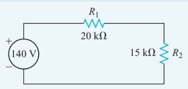
Figure 4 Circuit diagram for Example 2
Use ratios to find the voltage drop.
Since,
\[\frac{{{V}_{2}}}{E}=\frac{{{R}_{2}}}{{{R}_{T}}}\]
So,
\[{{V}_{2}}=E\frac{{{R}_{2}}}{{{R}_{T}}}=140V\times \frac{15k\Omega }{35k\Omega }=60V\]
Since the same current flows through all components of a series circuit, changing any one component affects the current through all the components. Therefore, control components such as switches, fuses, and rheostats are connected in series with a load, as shown in Figure 5.
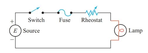
Figure 5 Control components in series with a load
The following characteristics can help us recognize a series circuit:
- The current is the same in all parts of a series circuit.
- The total resistance is the sum of all the individual resistances:
${{R}_{T}}={{R}_{1}}+{{R}_{2}}+{{R}_{3}}+\cdots $
- The applied voltage is equal to the sum of all the individual voltage drops:
$E={{V}_{1}}+{{V}_{2}}+{{V}_{3}}+\cdots $
- The ratios of voltage drop equal the ratios of resistances.
- A change to any component of a series circuit affects the current through all components.
Cells in Series
Most cells have a nominal voltage between 1.1 V and 1.5 V. The current rating of a cell depends on its size and type.
Identical cells connected in series provide higher voltages than a single cell. The current rating will be the same as for each individual cell since the current in a series circuit is the same in all parts of the circuit.
If cells with different capacities are connected in series, the lower capacity cells will be used up first. Most batteries for portable devices have cells connected in series, like those shown in Figure 6.
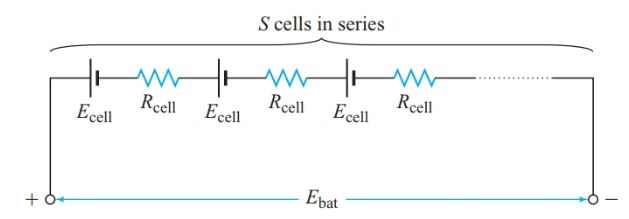
Figure 6 Equivalent circuit of a series-connected battery
If S is the number of cells connected in series, Ecell is the EMF of each cell, and Rcell is the internal resistance of each cell, then total battery EMF is
$\begin{matrix} {{E}_{bat}}=S{{E}_{bat}} & {} & \left( 3 \right) \\\end{matrix}$
and total battery internal resistance is
$\begin{matrix} {{R}_{bat}}=S{{R}_{cell}} & {} & \left( 4 \right) \\\end{matrix}$
Current in Series Circuit Example 3
How much current flows through an external resistance of 4.0 Ω connected to a battery consisting of ten cells connected in series with each cell having an EMF of 1.5 V and an internal resistance of 0.20 V? Find the terminal voltage of the battery.
Solution
\[\begin{align} & {{E}_{bat}}=S{{E}_{bat}}=10\times 1.5V=15V \\ & {{R}_{bat}}=S{{R}_{cell}}=10\times 0.20\Omega =2\Omega \\\end{align}\]
The total resistance in the circuit,
${{R}_{T}}={{R}_{bat}}+{{R}_{L}}=2+4=6\Omega $
Applying Ohm’s law to the whole circuit gives
$\begin{align} & I=\frac{{{E}_{bat}}}{{{R}_{T}}}=\frac{15V}{6\Omega }=2.5A \\ & {{V}_{T}}=I{{R}_{L}}=2.5A\times 4\Omega =10V \\\end{align}$
Figure 7 shows the equivalent circuit for the battery.
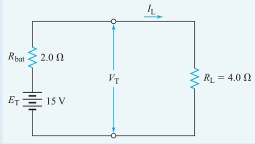
Figure 7 Equivalent circuit for Example 3
Series Circuit Key Takeaways
Understanding series circuit is fundamental in the study and application of electrical systems. These circuits demonstrate consistent behavior where the current remains the same across all components and the total resistance is the sum of individual resistances. Concepts such as Ohm’s Law, Kirchhoff’s Voltage Law, and voltage drop ratios are crucial tools for analyzing and designing such circuits. Their practical significance lies in real-world applications like controlling current flow with switches or fuses, distributing voltage evenly across devices, and ensuring system safety.