The article introduces the concept of parallel circuit, explaining their definition, characteristics, and how current and resistance behave within them. It also covers Ohm’s Law, Kirchhoff’s Current Law, conductance, and provides examples to demonstrate calculations for total current and equivalent resistance.
Figure 1 shows two different ways of drawing a circuit diagram for the same simple parallel circuit. Circuit diagrams usually show interconnecting conductors as either horizontal or vertical lines, as in Figure 1(a). However, to illustrate the nature of a parallel circuit, we redraw the circuit diagram by combining the junctions that are directly connected to each other, producing Figure 1(b).
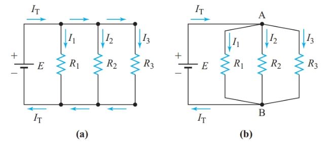
Figure 1 Simple parallel circuit: (a) Customary configuration, (b) Equivalent configuration
We can identify a parallel circuit by connections among the components. In Figure 1, E, R1, R2, and R3 are all in parallel because they are all connected between the same two points, A and B. Since each of the resistors is connected directly across the voltage source, V1 = V2 = V3 = E. We can omit the subscripts since the voltage is common to all the components connected in parallel.
Parallel Circuit Definition
Two or more electric components are in parallel in an electric circuit if a common voltage appears across all of the components.
For a series circuit, we determined the total resistance in order to find the current in the circuit. For a parallel circuit, we find the total current first and use it to determine the resistance of the circuit.
Given the applied voltage and the values of each resistance in the circuit of Figure 1, we can solve for the current in each branch by using Ohm’s law.
If we think of the current in each branch in terms of electrons flowing through the branch, it is apparent that the current through the source must be the sum of the branch currents.
In a simple parallel circuit, the total current is the sum of all the branch currents:
$\begin{matrix} {{I}_{T}}={{I}_{1}}+{{I}_{2}}+{{I}_{3}}+\cdots & {} & \left( 1 \right) \\\end{matrix}$
Equivalent Resistance Calculation Example 1
For the circuit in Figure 1, assume that R1 is 40 Ω, R2 is 30 Ω, R3 is 20 Ω, and E is 120 V. What single resistance would draw the same current from the source?
Solution
\[\begin{matrix} {{I}_{1}}=\frac{{{V}_{1}}}{{{R}_{1}}}=\frac{120V}{40\Omega }=3A \\ {{I}_{2}}=\frac{{{V}_{2}}}{{{R}_{2}}}=\frac{120V}{30\Omega }=4A \\ {{I}_{3}}=\frac{{{V}_{3}}}{{{R}_{3}}}=\frac{120V}{20\Omega }=6A \\\end{matrix}\]
${{I}_{T}}={{I}_{1}}+{{I}_{2}}+{{I}_{3}}=3+4+6=13A$
\[{{\operatorname{R}}_{eq}}=\frac{E}{{{I}_{T}}}=\frac{120V}{13A}=9.23\Omega \]
For a series circuit, the total resistance is greater than the resistance of any individual resistor. However, the resistance in a parallel circuit (e.g., the combination of resistors in Example 1) is less than the resistance of any individual resistor. Hence, when dealing with parallel circuits, we do not speak of total resistance. Instead, we speak of the equivalent resistance, Req, of two or more resistors in parallel.
Parallel circuits have characteristics that, in many respects, are similar but opposite to those of series circuits.
Kirchhoff’s Current Law
Kirchhoff extended the total-current principle of Equation 1 to apply to all electric circuits.
Kirchhoff’s current law: At any junction in a circuit, the algebraic sum of the currents entering the junction equals the algebraic sum of the currents leaving the junction.
Current in Parallel Circuit Example 2
Find the current in the R2 branch of the circuit of Figure 2.
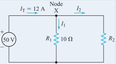
Figure 2 Circuit diagram for Example 2
Solution
\[{{I}_{1}}=\frac{V}{{{R}_{1}}}=\frac{50V}{10\Omega }=5A\]
The current flowing into junction X is IT and the currents flowing away from junction X are I1 and I2. Therefore,
$\begin{align} & {{I}_{T}}={{I}_{1}}+{{I}_{2}} \\ & {{I}_{2}}={{I}_{T}}-{{I}_{1}}=12-5=7A \\\end{align}$
Conductance
As Examples 1 and 2 demonstrate, the total current is always greater than the current through any branch of a parallel circuit. Therefore, the equivalent resistance is always less than the smallest of the branch resistances. The more resistors we connect in parallel, the smaller the equivalent resistance becomes.
In other words, the more resistors we connect in parallel, the more readily the circuit can pass current since there are more parallel branches for current to flow through.
Conductance is a measure of the ability of an electric circuit to pass current. The letter symbol for conductance is G.
The Siemens(S) is the SI unit of conductance: $1S=\frac{1}{1\Omega }$
Conductance is the reciprocal of resistance:
\[\begin{matrix} G=\frac{1}{R} & {} & \left( 2 \right) \\\end{matrix}\]
Where G is the conductance of a circuit in Siemens and R is the resistance of the same circuit in ohms.
Dividing both sides of Equation 1 by E (or V, since they are the same for simple parallel circuits), we get
\[\frac{{{I}_{T}}}{E}=\frac{{{I}_{1}}}{V}+\frac{{{I}_{2}}}{V}+\frac{{{I}_{3}}}{V}+\cdots \]
Substituting Ohm’s law into Equation 2 gives
\[G=\frac{1}{R}=\frac{1}{{V}/{I}\;}=\frac{I}{V}\]
Therefore,
$\begin{matrix} {{G}_{T}}={{G}_{1}}+{{G}_{2}}+{{G}_{3}}+\cdots & {} & \left( 3 \right) \\\end{matrix}$
In parallel circuits, the total conductance is equal to the sum of the conductance of all the individual branches.
The equivalent resistance is simply Req = 1/GT.
We can use conductance to find the equivalent resistance for a parallel circuit without calculating the total current.
Example 1A
For the circuit in Figure 1, assume that R1 is 40 Ω, R2 is 30 Ω, R3 is 20 Ω, and E is 120 V. What single resistance would draw the same current from the source?
Solution
$\begin{align} & {{G}_{T}}={{G}_{1}}+{{G}_{2}}+{{G}_{3}}=\frac{1}{40\Omega }+\frac{1}{30\Omega }+\frac{1}{20\Omega }=0.1083S \\ & {{\operatorname{R}}_{eq}}=\frac{1}{{{G}_{T}}}=\frac{1}{0.1083S}=9.23\Omega \\\end{align}$
When only two resistors are connected in parallel, Equation 3 becomes
\[{{G}_{T}}={{G}_{1}}+{{G}_{2}}=\frac{1}{R1}+\frac{1}{{{R}_{2}}}=\frac{{{R}_{1}}+{{R}_{2}}}{{{R}_{1}}\times {{R}_{2}}}\]
and
\[\begin{matrix} {{\operatorname{R}}_{eq}}=\frac{{{R}_{1}}\times {{R}_{2}}}{{{R}_{1}}+{{R}_{2}}} & {} & \left( 4 \right) \\\end{matrix}\]
For two resistors in parallel, the equivalent resistance equals their product over their sum.
We can rearrange Equation 4 to find the resistance R2 that we must connect in parallel with a given resistance R1 to obtain a desired equivalent resistance:
\[\begin{matrix} {{\operatorname{R}}_{2}}=\frac{{{R}_{1}}\times {{R}_{eq}}}{{{R}_{1}}-{{R}_{eq}}} & {} & \left( 5 \right) \\\end{matrix}\]
Now we can use Ohm’s law and Kirchhoff’s current law to find the current through resistor R2:
\[\begin{align} & {{V}_{1}}={{V}_{2}}={{I}_{1}}{{R}_{1}}={{I}_{2}}{{R}_{2}} \\ & {{I}_{1}}{{R}_{1}}=\left( {{I}_{T}}-{{I}_{2}} \right){{R}_{1}} \\\end{align}\]
\[\begin{matrix} {{I}_{2}}={{I}_{T}}\times \left( \frac{{{R}_{1}}}{{{R}_{1}}+{{R}_{2}}} \right) & {} & \left( 6 \right) \\\end{matrix}\]
When N equal resistors are connected in parallel, we can show that
\[\begin{matrix} {{\operatorname{R}}_{eq}}=\frac{R}{N} & {} & \left( 7 \right) \\\end{matrix}\]
Where R is the resistance of each of the parallel resistors and N is the number of resistors.
Example 3
What is the equivalent resistance of a 1-kV and a 4-kV resistor in parallel?
Solution
\[{{\operatorname{R}}_{eq}}=\frac{{{R}_{1}}\times {{R}_{2}}}{{{R}_{1}}+{{R}_{2}}}=\frac{1k\Omega \times 4k\Omega }{\left( 1k\Omega +4k\Omega \right)}=0.8k\Omega \]
We defined resistivity as the resistance of a unit length and cross-section of a material. Conductivity is defined in a similar way.
The conductivity of a material is the conductance of a unit length and cross-section of that material. The letter symbol for conductivity is the Greek letter σ (sigma). Conductivity is measured in Siemens per meter.
Since conductance is the reciprocal of resistance, conductivity is the reciprocal of resistivity:
\[\begin{matrix} \sigma =\frac{1}{\rho } & {} & \left( 8 \right) \\\end{matrix}\]
- You May Also Read: Series Circuit: Definition & Examples | Resistors in Series
Characteristics of Parallel Circuits
Since V = IR and R = 1/G, V = I/G. The voltage is the same across all components connected in parallel, so
\[\begin{matrix} V=\frac{{{I}_{T}}}{{{G}_{T}}}=\frac{{{I}_{1}}}{{{G}_{1}}}=\frac{{{I}_{2}}}{{{G}_{2}}}=\frac{{{I}_{3}}}{{{G}_{3}}}=\cdots \begin{matrix} {} & {} & {} \\\end{matrix} & {} & \left( 9 \right) \\\end{matrix}\]
By transposing variables in each pair of equal terms, we get
\[\begin{matrix} \frac{{{I}_{1}}}{{{I}_{2}}}=\frac{{{G}_{1}}}{{{G}_{2}}} & , & \begin{matrix} \frac{{{I}_{2}}}{{{I}_{3}}}=\frac{{{G}_{2}}}{{{G}_{3}}}=\frac{{{R}_{3}}}{{{R}_{2}}} & , & \text{and so on} \\\end{matrix} \\\end{matrix}\]
In a parallel circuit, the ratio between any two branch currents equals the ratio of their conductance or the inverse of the ratio of their resistances.
Example 4
The total current drawn by a 12.5-kV resistor and a 50-kV resistor in parallel is 15 mA. Find the current through the 50-kV resistor.
Solution
From the circuit diagram of Figure 3,
${{I}_{1}}+{{I}_{2}}=15mA$$\begin{align} & \frac{{{I}_{1}}}{{{I}_{2}}}=\frac{{{R}_{2}}}{{{R}_{1}}}=\frac{50k\Omega }{12.5k\Omega }=4 \\ & {{I}_{1}}=4{{I}_{2}} \\\end{align}$
Substituting for I1 in the first equation gives
$\begin{align} & 4{{I}_{2}}+{{I}_{2}}=15mA \\ & {{I}_{2}}=\frac{15mA}{5}=3mA \\\end{align}$
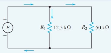
Figure 3 Circuit diagram for Example 4
When the internal resistance of the source is negligible, altering the resistance of one branch of a parallel circuit does not affect the voltage across, or the current through, the other branches. Therefore, changes in one branch of a parallel circuit have a negligible effect on the other branches.
In-house wiring, lighting circuits are connected in parallel so that switching one circuit on or off does not affect the operation of the other circuits (see Figure 4).
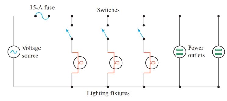
Figure 4 Parallel connection of loads in house wiring
The following characteristics can help us recognize parallel circuits:
- The voltage is the same across all components.
- The total conductance is the sum of all the individual branch conductance:
${{G}_{T}}={{G}_{1}}+{{G}_{2}}+{{G}_{3}}+\cdots $
- The total current is the sum of all the individual branch currents:
${{I}_{T}}={{I}_{1}}+{{I}_{2}}+{{I}_{3}}+\cdots $
- The ratio between branch currents is the same as the conductance ratio and the inverse of the resistance ratio.
- Each branch is independent of any changes in the other branches, providing the voltage across the parallel circuit is constant.
Cells in Parallel
A battery of identical cells connected in parallel (see Figure 5) has the same EMF as a single cell but can deliver a greater maximum current.
The total capacity of the battery is proportional to the number of cells. If the cells do not all have the same EMF, currents will flow between them since the cells with lower EMFs will act as loads for the cells with higher EMFs.
Standard AA-size cells are sometimes connected in parallel to make a compact battery with enough current capacity to run motors in devices such as cordless electric razors.
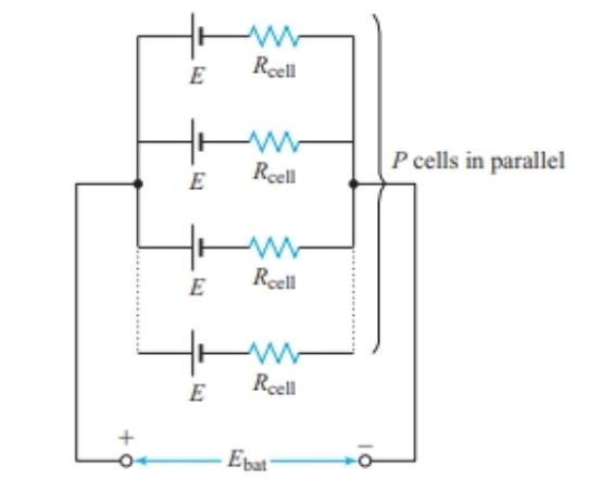
Figure 5 Equivalent circuit of a parallel connected battery
In Figure 5, P is the number of cells connected in parallel, Ecell is the EMF of each cell, and Rcell is the internal resistance of each cell. The battery EMF is
Ebat = E
and the total internal resistance of the battery is
\[\begin{matrix} {{R}_{bat}}=\frac{{{R}_{cell}}}{P} & {} & \left( 10 \right) \\\end{matrix}\]
Example 5
How much current flows through an external resistance of 4.00 V connected to a battery consisting of ten cells connected in parallel, with each cell having an EMF of 1.50 V and an internal resistance of 0.20 V? Find the terminal voltage of the battery.
Solution
$\begin{align} & {{E}_{bat}}=1.5V \\ & {{R}_{bat}}=\frac{{{R}_{cell}}}{P}=\frac{0.20\Omega }{10}=0.020\Omega \\ & I=\frac{E}{{{R}_{T}}}=\frac{1.5}{4\Omega +0.020\Omega }=1.49V \\ & VT=I{{R}_{L}}=0.373A\times 4\Omega =1.49V \\\end{align}$
Figure 6 shows an equivalent circuit for the battery.
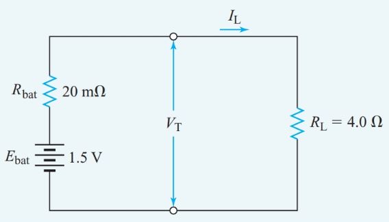
Figure 6 Equivalent circuit for Example 5
Parallel Circuit Key Takeaways
Understanding parallel circuit is fundamental in both theoretical and practical aspects of electrical engineering and electronics. Their unique characteristics—such as equal voltage across branches, reduced equivalent resistance, and increased total current—enable more efficient distribution of power. Applications ranging from household wiring systems to complex electrical networks in industrial settings rely heavily on these principles. Ohm’s Law, Kirchhoff’s Current Law, and conductance calculations provide essential tools for designing, troubleshooting, and optimizing these systems.