The article provides an overview of series-parallel circuit, including their definition, how to analyze them using equivalent resistance methods, and examples demonstrating voltage, current, and power calculations. It also explains the voltage-divider principle and its applications in electronic circuits, particularly in designing power supplies and managing voltage levels for various loads.
Considered as a whole, the circuit in Figure 1 is neither a series nor a parallel circuit. However, R2 and R3 are connected between the same two points in the circuit and must have the same voltage drop. Therefore these two resistors are in parallel, and we can calculate a single equivalent resistance for them.
As measured from the terminals of the voltage source, the simplified circuit of Figure 2 is equivalent to the original circuit of Figure 1. In Figure 2, R1 is in series with the equivalent resistance of R2 and R3 in parallel. Therefore, we can solve the circuit of Figure 2 as a simple series circuit.
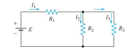
Figure 1 Simple series-parallel circuit
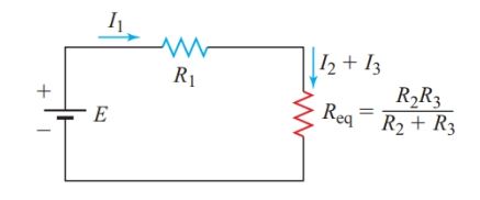
Figure 2 Equivalent circuit for Figure 1
In the circuit shown in Figure 3(a), R2 and R3 have the same current through them and are therefore in series. We can replace them with an equivalent resistor, as shown in Figure 3(b). We can now solve the simplified circuit of Figure 3(b) as a simple parallel circuit.
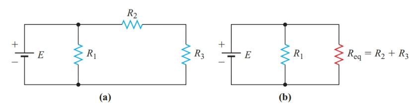
Figure 3 (a) Series-parallel circuit; (b) Equivalent circuit
Series-Parallel Circuit Definition
We define a series-parallel circuit as one in which some portions of the circuit have the characteristics of simple series circuits while the other portions have the characteristics of simple parallel circuits.
- You May Also Read: Series Circuit: Definition & Examples | Resistors in Series
Series-Parallel Circuit Solution using Equivalent-Circuit Method
We can solve series-parallel circuits by substituting the equivalent resistances for various portions of the circuit until the original circuit is reduced to either a simple series or a simple parallel circuit.
Example 1
Find the voltage drop, current, and power for each resistor in the circuit diagram of Figure 4.
Solution
Step 1
Draw a fully labeled schematic diagram for this particular circuit.
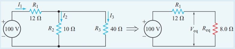
Figure 4 Circuit diagram for Example 1
Step 2
Since R2 and R3 are in parallel,
\[{{\operatorname{R}}_{eq}}=\frac{{{R}_{3}}\times {{R}_{3}}}{{{R}_{2}}+{{R}_{3}}}=\frac{10\times 40}{10+40}=8\Omega \]
The total resistance of the circuit is
${{R}_{T}}={{R}_{1}}+{{\operatorname{R}}_{eq}}=12+8=20\Omega $
Step 3
From Ohm’s law,
\[{{I}_{T}}=\frac{E}{{{R}_{T}}}=\frac{100V}{20\Omega }=5A\]
Step 4
Since R1 is in series with the source,
${{I}_{1}}={{I}_{T}}=5A$
Step 5
Applying Ohm’s law to R1,
${{V}_{1}}={{I}_{1}}{{R}_{1}}=5A\times 12\Omega =60V$
Step 6
From Kirchhoff’s voltage law,
${{V}_{eq}}=E-{{V}_{1}}=100-60=40V$
Returning now to the original circuit,
${{V}_{2}}={{V}_{3}}={{V}_{eq}}=40V$
Step 7
Applying Ohm’s law to R2 and R3,
$\begin{align} & {{I}_{2}}=\frac{{{V}_{2}}}{{{R}_{2}}}=\frac{40V}{10\Omega }=4A \\ & {{I}_{3}}=\frac{{{V}_{3}}}{{{R}_{3}}}=\frac{40V}{40\Omega }=1A \\\end{align}$
To verify our calculations, we can check that the currents we calculated satisfy Kirchhoff’s current law for this circuit:
${{I}_{1}}={{I}_{2}}+{{I}_{3}}$
Step 8
Since,
$P=VI$
So,
$\begin{align} & {{P}_{1}}={{V}_{1}}{{I}_{1}}=60V\times 5A=0.30kW \\ & {{P}_{2}}={{V}_{2}}{{I}_{2}}=40V\times 4A=0.16kW \\ & {{P}_{1}}={{V}_{1}}{{I}_{1}}=40V\times 1A=40W \\ & {{P}_{1}}={{V}_{1}}{{I}_{1}}=100V\times 5A=0.50kW \\\end{align}$
We can verify our calculations by checking that:
${{P}_{T}}={{P}_{1}}+{{P}_{2}}+{{P}_{3}}$
Voltage-Divider Principle
For the series circuit of Figure 5, Kirchhoff’s voltage law states that E = V1 + V2 + V3. In other words, the total applied voltage is divided among the three resistors. We can connect a voltmeter across six possible combinations of the terminals A, B, C, and D, as shown in Figure 5. Thus, the series combination of R1, R2, and R3 acts as a voltage divider.
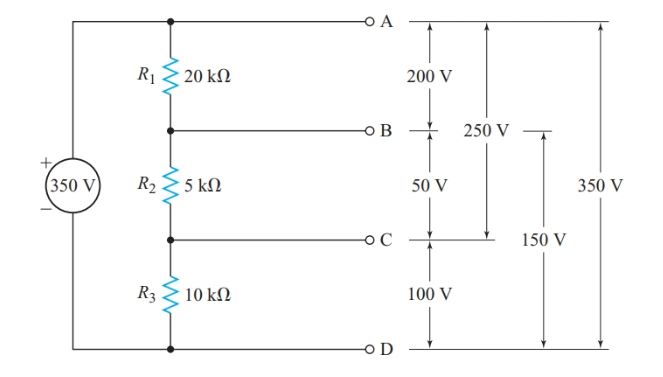
Figure 5 Voltage-divider principle
To solve for the six voltages in Figure 5, we could calculate RT, find I from Ohm’s law, and then calculate the voltage drop across each resistance from V1 = IR1, V2 = IR2, and so on. However, we can calculate each voltage in a single step. A property of series circuits that is often called the voltage-divider principle:
In a series circuit, the ratio between any two voltage drops equals the ratio of the two resistances across which these voltage drops occur.
Hence, for any resistor Rn in a voltage divider,
\[\begin{align} & \frac{{{V}_{n}}}{E}=\frac{{{R}_{n}}}{{{R}_{T}}} \\ & and \\ & \begin{matrix} {{V}_{n}}=E\times \frac{{{R}_{n}}}{{{R}_{T}}} & {} & \left( 1 \right) \\\end{matrix} \\\end{align}\]
Example 2
What is the voltage between terminals B and D in the circuit of Figure 5?
Solution
\[\begin{align} & {{V}_{BD}}=E\times \frac{{{R}_{2}}+{{R}_{3}}}{{{R}_{1}}+{{R}_{2}}+{{R}_{3}}} \\ & =350V\times \frac{\left( 5k\Omega +10k\Omega \right)}{\left( 20k\Omega +5k\Omega +10k\Omega \right)} \\ & =150V \\\end{align}\]
Using a variable resistor as a voltage divider provides a continuously variable terminal voltage, as shown in Figure 6.
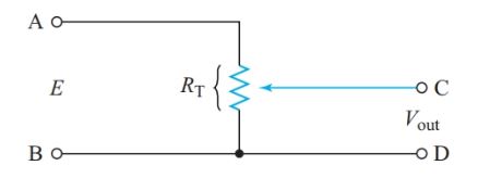
Figure 6 Potentiometer circuit
Voltage Dividers
Voltage dividers are widely used in power supplies for electronic circuits so that a single voltage source can supply all the various voltages required by a piece of equipment, reducing the cost, size, and weight of the equipment.
The series-dropping resistor of Figure 7 provides the simplest method of obtaining the required voltage drop across a particular circuit element.
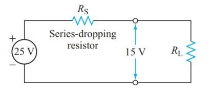
Figure 7 Series-dropping resistor
Example 3
A portion of an electronic circuit requires an operating voltage of 15 V and a current of 20 mA. If the supply terminal voltage is 25 V, what value of the series-dropping resistor is required?
Solution
From Ohm’s law, we can represent this load circuit by a resistor, as in Figure 7.
\[{{R}_{L}}=\frac{{{V}_{L}}}{{{I}_{L}}}=\frac{15V}{20mA}=750\Omega \]
From Kirchhoff’s voltage law, the voltage drop across the series- dropping resistor must be
${{V}_{D}}=E-{{V}_{L}}=25-15=10V$
Since the dropping resistor and the load are in series,
$\begin{align} & {{I}_{D}}={{I}_{L}}=20mA \\ & {{R}_{S}}=\frac{{{V}_{D}}}{{{I}_{D}}}=\frac{10V}{20mA}=500\Omega \\\end{align}$
To complete the design, we find the minimum power rating for RS:
$P=VI=10V\times 20mA=0.20W$
A 0.5-W resistor would be a good choice since it will operate at a lower temperature than a 0.25-W resistor and thus be less likely to fail.
The advantage of the simple series-dropping resistor is that the only drain on the power supply is the current through the load. But this circuit has the disadvantage that any change in load resistance changes the current through the series-dropping resistor, which, in turn, changes the voltage drop across the resistor and the voltage supplied to the load.
In circuits where the load is a transistor, RL can become very high. Under such circumstances, the voltage drop across a series-dropping resistor is almost zero and the voltage across the load is close to the full applied voltage, which may be high enough to damage the transistor.
To prevent such damage, some voltage-divider designs include a bleeder resistor in parallel with the load, as in Figure 8. The bleeder resistor ensures there is always enough current through the series-dropping resistor to maintain an appreciable voltage drop across it. Hence, the load voltage cannot rise to the full applied voltage.
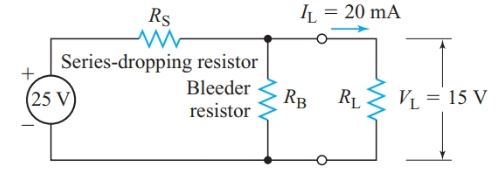
Figure 8 Voltage divider with a bleeder resistor
In power supplies for electronic equipment, a bleeder current of 10–25% of the total current drawn from the source provides sufficient protection against excessive load voltage when the load resistance increases.
The greater the bleeder current, the fewer variations in load current affect the load voltage. Thus, improved voltage regulation is achieved at the expense of extra current drain from the source and extra heat produced in the voltage-divider resistors.
In designing voltage dividers for loads consisting of a single transistor, voltage regulation is more significant than a few extra milliamperes of bleeder current.
In circuits that obtain several different voltages from one power supply, it is convenient to have a common reference point for all voltage measurements.
Often the circuit’s metal frame or chassis is connected to the circuit and used as the reference point. The chassis may also be connected to the earth, usually through the ground wire of the electrical system.
- You May Also Read: Parallel Circuit: Definition & Examples | Resistors in Parallel
The symbol at the bottom of Figure 9 indicates that the reference point is grounded. Hence, we can say that the voltage at point A is 1250 V with respect to ground. The symbol in the middle of Figure 10 indicates the point where the chassis is electrically connected to the circuit.
With respect to chassis, the voltage at point A in this circuit is 112 V and the voltage at point B is 212 V.
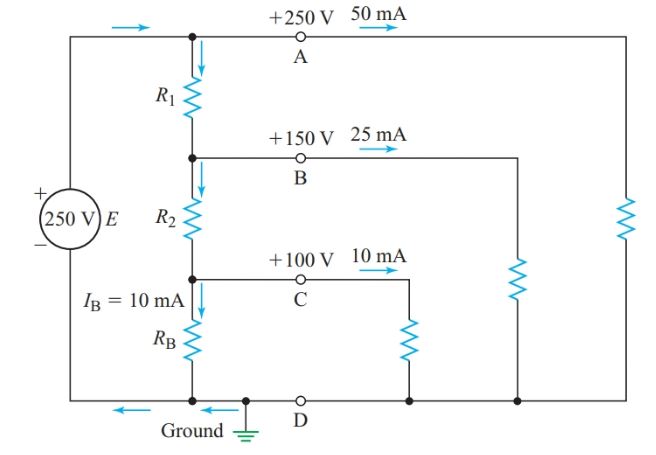
Figure 9 Voltage divider with multiple output voltages
Transistor circuits can require positive or negative voltages relative to a common chassis connection, and many circuits require both. We can obtain these positive and negative voltages from one power supply by connecting a tap on a voltage divider to the chassis as shown in Figure 10.
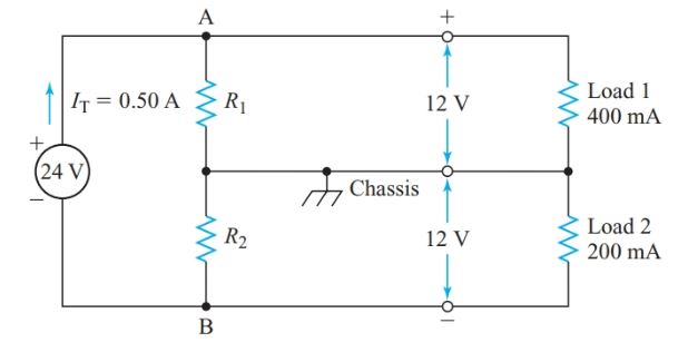
Figure 10 Power-supply voltage divider for a transistor amplifier
Example 5
At full load, the power supply in Figure 10 has a terminal voltage of 24 V DC. Design a voltage divider to provide 112 V and 212 V with respect to the chassis when the current drains are 400 mA at 112 V and 200 mA at 212 V. The total current drain on the power supply is 500 mA.
Solution
Since R1 is in parallel with load 1, V1 5 12 V. Applying Kirchhoff’s current law to junction A,
$\begin{align} & I1=200mA-400mA=100mA \\ & {{R}_{1}}=\frac{{{V}_{1}}}{{{I}_{1}}}=\frac{12V}{100mA}=120\Omega \\ & P1={{V}_{1}}{{I}_{1}}=12V\times 100mA=1.2W \\\end{align}$
Similarly,
$\begin{align} & {{V}_{2}}=12V, \\ & and \\ & {{I}_{2}}=500mA-200mA=300mA \\ & {{R}_{2}}=\frac{12V}{300mA}=40\Omega \\ & {{P}_{2}}=12V\times 300mA=3.6W \\\end{align}$
Current-Divider Principle
The current-divider principle can be described as:
In a parallel circuit, the ratio between any two branch currents equals the ratio of the two conductance through which these currents flow.
Since the voltage is common for resistors in parallel,
\[V=\frac{{{I}_{1}}}{{{G}_{1}}}=\frac{{{I}_{2}}}{{{G}_{2}}}=\frac{{{I}_{n}}}{{{G}_{n}}}=\frac{{{I}_{T}}}{{{G}_{T}}}\]
And
\[\begin{matrix} {{I}_{n}}={{I}_{T}}\times \frac{{{G}_{n}}}{{{G}_{T}}} & {} & \left( 2 \right) \\\end{matrix}\]
Substituting Gn = 1/Rn, and GT = 1/Req in Equation 2 gives
\[\begin{matrix} {{I}_{n}}={{I}_{T}}\times \frac{{{\operatorname{R}}_{eq}}}{{{R}_{n}}} & {} & \left( 3 \right) \\\end{matrix}\]
Hence, we can restate the current-divider principle:
In a parallel circuit, the ratio between any two branch currents is the inverse of the ratio of the branch resistances.
For two resistors in parallel,
$\begin{align} & {{\operatorname{R}}_{eq}}=\frac{{{R}_{1}}\times {{R}_{2}}}{{{R}_{1}}+{{R}_{2}}} \\ & {{I}_{1}}={{I}_{T}}\times \frac{{{R}_{1}}\times {{R}_{2}}}{{{R}_{1}}\left( {{R}_{1}}+{{R}_{2}} \right)} \\\end{align}$
And
\[\begin{align} & \begin{matrix} {{I}_{1}}={{I}_{T}}\times \frac{{{R}_{2}}}{\left( {{R}_{1}}+{{R}_{2}} \right)} & {} & \left( 4 \right) \\\end{matrix} \\ & similarly, \\ & \begin{matrix} {{I}_{1}}={{I}_{T}}\times \frac{{{R}_{1}}}{\left( {{R}_{1}}+{{R}_{2}} \right)} & {} & \left( 5 \right) \\\end{matrix} \\\end{align}\]
Example 6
Calculate the bleeder current in the voltage divider if the load resistance is 3.0 kΩ, as shown in Figure 11.
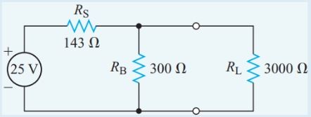
Figure 11 Circuit diagram for Example 6
Solution
The equivalent resistance of the bleeder resistor and the load resistance in parallel is
$\begin{align} & {{\operatorname{R}}_{eq}}=\frac{{{R}_{1}}\times {{R}_{2}}}{{{R}_{1}}+{{R}_{2}}}=\frac{300\Omega \times 3k\Omega }{300\Omega +3k\Omega }=273\Omega \\ & {{R}_{T}}={{\operatorname{R}}_{eq}}+{{R}_{S}}=143+273=416\Omega \\ & {{I}_{T}}=\frac{E}{{{R}_{T}}}=\frac{25V}{416\Omega }=60.1mA \\ & {I}_{B}={{I}_{T}}\times \frac{{{R}_{L}}}{{{R}_{B}}+{{R}_{L}}}=60.1mA\times \frac{3k\Omega }{3.3k\Omega }=55mA \\\end{align}$
Cells in Series-Parallel
A series-parallel battery connection, as shown in Figure 12, provides both greater voltage and greater capacity than the individual cells. The cells must be identical to avoid circulating currents within the battery. The total capacity of the battery is determined by the number of rows connected in parallel.
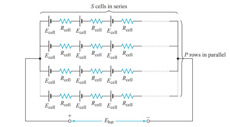
Figure 12 Equivalent circuit of a series-parallel connected battery
For a battery consisting of P parallel rows with S cells in series in each row, the EMF of the battery is the EMF of one series row, the same as for a series battery connection:
${{E}_{bat}}=S{{E}_{cell}}$
The total internal resistance is the combination of P identical parallel rows of S resistors in series, with each resistor having a resistance of Rcell, so
\[\begin{matrix} {{R}_{bat}}=\frac{resistance\text{ }of\text{ }each\text{ }row}{number\text{ }of\text{ }rows}=\frac{S{{R}_{cell}}}{P} & {} & \left( 6 \right) \\\end{matrix}\]
Example 7
Twenty identical cells are connected in four parallel rows, each with five cells in series. Each cell has an internal resistance of 0.20 V. The battery delivers a current of 5.0 A to a 1.25-V resistor as shown in Figure 13. Calculate the EMF of each cell.
Solution
$\begin{align} & {{R}_{bat}}=\frac{S{{R}_{cell}}}{P}=\frac{5\times 0.20\Omega }{4}=0.25\Omega \\ & {{E}_{bat}}={{I}_{L}}{{R}_{T}}=5A\times \left( 0.25\Omega +1.25\Omega \right)=7.5V \\ & {{E}_{cell}}=\frac{{{E}_{bat}}}{S}=\frac{7.5V}{5}=1.5V \\\end{align}$
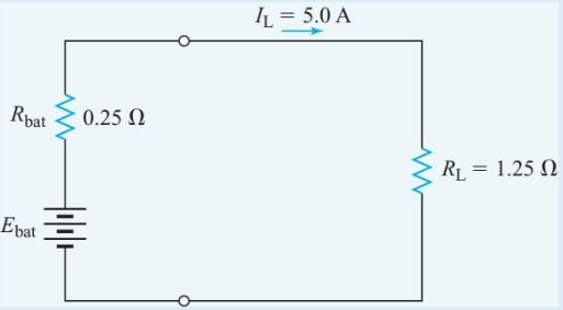
Figure 13 Equivalent circuit for Example 7
Series-Parallel Circuit Key Takeaways
Understanding series-parallel circuit and the voltage-divider principle is essential for designing and analyzing practical electronic systems. These concepts provide a foundational framework for calculating current, voltage, and power in complex circuits by simplifying them into manageable sections. Applications such as power supply design, voltage regulation, and load management heavily rely on these principles to ensure devices operate within safe and efficient voltage levels. Series-parallel analysis also allows engineers to predict circuit behavior, optimize energy consumption, and protect sensitive components like transistors from damage due to voltage fluctuations.