The article explains how inductors behave in both DC and AC circuits, emphasizing the principles of electromagnetic induction, Lenz’s law, and the concept of inductive reactance. It also covers how current responds to varying frequencies, and how inductors function when arranged in series or parallel configurations.
When a coil of wire (an inductor) is connected to DC electricity (Figure 1), a current is building up from zero, making a magnetic field. The wire, itself, is in that field, and therefore, a voltage is generated in it. This generated voltage is in the opposite direction of the voltage making the field; thus, it is opposing the current. The same thing happens when an inductor is disconnected from a DC source.
The phenomenon just discussed is called Lenz’s law.
Before a statement for Lenz’s law is made, let’s define the term induction. When an electromagnetic force (emf) is generated in an inductor, a more common statement employed is that “an emf is induced in the inductor.” Thus, induction is used instead of generation, which goes well with inductor and inductance.
Lenz’s law states that an induced emf always opposes its cause, meaning that the direction of the current owing to the induced voltage is opposite to the direction of the current that made the induction. As a result of this opposition, the current in a DC circuit containing an inductor after a switch is turned on is not an abrupt change and, instead, is a gradual growth from zero to a steady value. This is illustrated in Figure 2.
Induction: Generation of electricity in a wire when the magnetic flux is cut by the wire (e.g., when the wire moves with respect to a magnetic field or the strength and/or direction of the magnetic field varies).
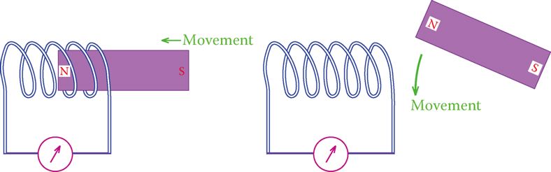
Figure 1: Moving a magnet near a coiled wire induces electricity in the coil.
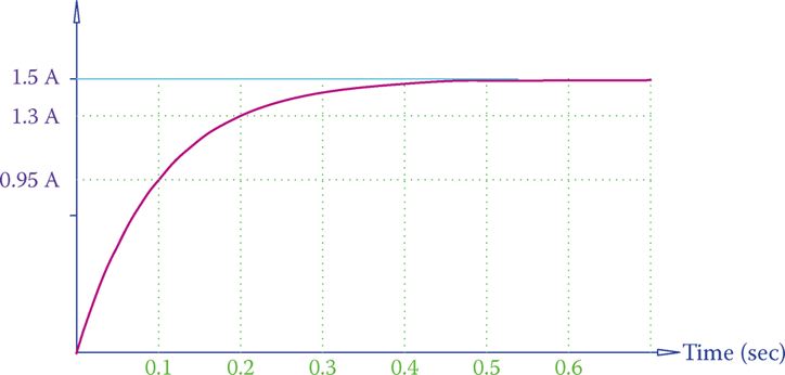
Figure 2 Gradual change of current from zero to 1.5 A in a circuit containing a coil.
As can be observed, it takes a short time for the current to settle to its steady value. The steady value of the current depends on the total resistance in the circuit.
The length of time that takes for the current to reach its final value depends on (1) the value of inductance of the coil (measured in henries) and (2) the total resistance of the circuit (measured in ohm).
Inductor Connected to AC
For the sake of better understanding, first, let’s assume a square wave AC signal provided by a source and connected to an inductor, shown in Figure 3. Furthermore, we assume that the resistance of the coil is negligible and can be ignored.
When the circuit containing an inductor is turned on, a current starts to develop in the circuit, starting from zero and reaching a high value, according to the curve as shown in Figure 2.
But, before the current reaches its maximum value the voltage has a sudden change and the polarity changes. Consequently, a current in the opposite direction starts to develop in the same manner.
On the basis of the gradual development of current and the fact that the AC voltage switches back and forth from negative to positive and vice versa, it is easy to understand that for the circuit of Figure 3 the current looks as illustrated in Figure 4. It can be further understood from Figure 4 that
- There is always a current flowing in the circuit.
- Current changes between positive and negative, i.e., it is AC.
- Current has its maximum (and minimum) value at the time that the voltage is zero (points A, A′, A″, etc., and points B, B′, B″, etc.).
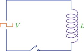
Figure 3 Inductor connected to an AC source with a square waveform.
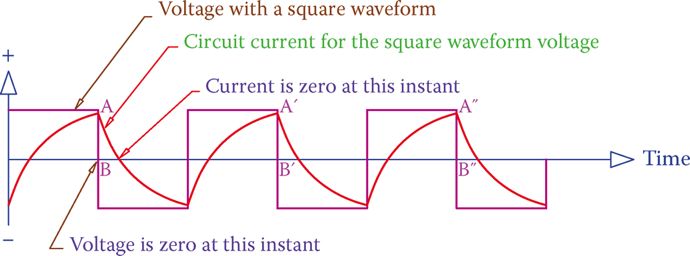
Figure 4 Current in an inductor connected to an AC source with a square waveform.
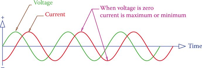
Figure 5 Current in an inductor connected to an AC source with a sinusoidal waveform.
If instead of a square wave, we have a sinusoidal AC waveform, which is the common case, the current is also sinusoidal and looks like Figure 5. Its peaks correspond to the instants the voltage value is zero.
Note that, as depicted in Figure 5, in an AC circuit containing an inductor (only) the current is 90° behind the applied voltage. This means that the current reaches its maximum (minimum) after the voltage has reached its maximum (minimum), and the difference between the time that voltage reaches its peak and the time that current reaches its peak is 1/4 of a cycle or 90°. This is always the case for such a circuit.
AC Current in an Inductor
We established that when an inductor is connected to an AC source, a current exists in the circuit. This implies that, on the basis of Ohm’s law, there is some resistance (to electric flow) in the circuit associated with this current. This so-called resistance (it is not really resistance because there is zero ohm value in the circuit, as assumed) can be determined.
But, first, let’s establish another fact that the current in this circuit changes with the frequency of the AC electricity. This can be easily understood from the comparison of currents shown for two cases in Figure 6.
Again, for better understanding, a square waveform is assumed. The waveform in Figure 6b has 2× the frequency as in Figure 6a. The current in Figure 6b is smaller than the current in Figure 6a. The reason for the difference in the value of current is that in Figure 6b there is not sufficient time for reaching the peak value before the polarity switching occurs. The same is true for a sinusoidal waveform.
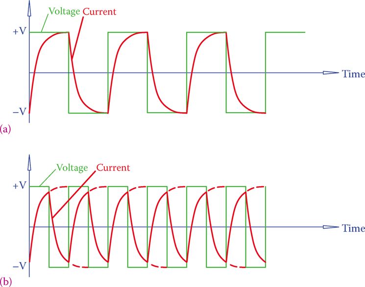
Figure 6 Comparison of currents in two AC square wave signals when frequency doubles. (a) Lower frequency: larger peak current. (b) Higher frequency: smaller peak current.
It can be followed from Figure 6 that the current through an inductor has an inverse effect with the frequency of the AC line.
The effect of the insertion of an inductor in an AC circuit is exhibited in the form of impedance to the current, but because it is not a resistance (with ohm value that can be measured), it is called reactance.
So, a reactance in an AC circuit is what exhibits a resistance to the flow of current, but it is not because of a resistive element that converts the electrical energy to heat. Reactance is measured in ohms. To specify that reactance is due to an inductor, when necessary, it is more particularly addressed as inductive reactance.
The reactance of an inductor, denoted by XL, depends on the frequency and the inductance and can be found from
Reactance: The apparent resistance (measured in ohms) that a capacitor or an inductor when connected in an AC circuit exhibits to the flow of electricity. Reactance depends on AC frequency and unlike a resistor, the energy involved does not convert to heat.
Inductive reactance: The apparent resistance to the flow of electricity exhibited by an inductor in an AC circuit. It is measured in ohm and determines the current in the inductor based on the applied voltage.
$\begin{matrix} {{X}_{L}}=2\pi fL & {} & \left( 1 \right) \\\end{matrix}$
Where π is a constant (π = 3.14159265), f is the frequency of the AC electricity measured in Hz, and L is the inductance measured in henries.
Inductive Reactance Calculation Example 1
What is the inductive reactance of an inductor when connected to 60 Hz electricity? The inductor has an inductance of 0.05 H.
Solution
It follows directly from Equation 1 that
${{X}_{L}}=2\pi fL=2\pi *60*0.05=18.85\Omega $
Inductor Current Calculation Example 2
Find the current for an inductor when connected to a 9 V, 50 Hz AC power source, if its inductance is 20 mH.
Solution
$\begin{align} & {{X}_{L}}=2\pi L=2\pi *50*0.020=6.28\Omega \\ & I={}^{9}/{}_{6.28}=1.43A \\\end{align}$
Inductor Current Calculation Example 3
What is the current in the inductor in Example 2 if the frequency of the power source is 60 Hz?
Solution
$\begin{align} & {{X}_{L}}=2\times 3.14\times 60\times 0.020=7.64\Omega \\ & I={}^{9}/{}_{7.54}=1.19A \\\end{align}$
You can observe from the above examples that when the frequency goes up, the reactance of an inductor goes up proportionally to it and the current in the inductor decreases.
When the frequency of electricity connected to an inductor goes up, the reactance of the inductor increases proportionally to the frequency and the current through the inductor decreases.
Inductors in Series
In the same way that resistors could be combined in series and in parallel with each other, inductors can be put in series or in parallel, when necessary. Figure 7 illustrates three inductors in series. The relationships for a number of inductors put in series with each other are
\[\begin{matrix} L={{L}_{1}}+{{L}_{2}}+{{L}_{3}}+\cdots & {} & \left( 2 \right) \\\end{matrix}\]
\[\begin{matrix} {{X}_{L}}={{X}_{{{L}_{1}}}}+{{X}_{{{L}_{2}}}}+{{X}_{{{L}_{3}}}}+\cdots & {} & \left( 3 \right) \\\end{matrix}\]
L is the equivalent inductor for all the inductors in series, and XL is the equivalent inductive reactance of them.

Figure 7 Inductors in series.
When inductors are connected in series, all of them share the same current. Accordingly, similar to the case for resistors, the total voltage divides among them, proportional to their reactance values.
Current in Series Inductors Example 4
What is the current in three inductors in series, when the applied voltage is 48 V? The frequency of the power supply is 60 Hz, and the inductors are 5, 10, and 15 mH.
Solution
For this problem, either Equation 2 or 3 can be used. Using the former takes less calculation because similar calculations must be repeated for each inductor to find its reactance.
$\begin{align} & L=5+10+15=30mH \\ & {{X}_{L}}=2\pi *60*0.030=11.31\Omega \\ & I={}^{48}/{}_{11.31}=4.24A \\\end{align}$
Inductors in Parallel
If one needs to connect inductors in parallel with each other, as shown in Figure 8, then the rule of parallel inductors can be used. You have noticed that the rule for inductors in series is the same as that used for resistors in series. The same is true for inductors in parallel with each other. Either of the following equations can be used.
\[\begin{matrix} \frac{1}{L}=\frac{1}{{{L}_{1}}}+\frac{1}{{{L}_{2}}}+\frac{1}{{{L}_{3}}}+\cdots & {} & \left( 4 \right) \\\end{matrix}\]
\[\begin{matrix} \frac{1}{{{X}_{L}}}=\frac{1}{{{X}_{{{L}_{1}}}}}+\frac{1}{{{X}_{{{L}_{2}}}}}+\frac{1}{{{X}_{{{L}_{3}}}}}+\cdots & {} & \left( 5 \right) \\\end{matrix}\]
Current in Parallel Inductors Example 5
Three inductors with inductance 5, 10, and 15 mH are put in parallel with each other and connected to 120 V line. If the frequency of the line is 60 Hz, what is the current in the line?
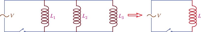
Figure 8 Inductors in parallel.
Solution
For this problem, it is easier to use Equation 4.
\[\frac{1}{L}=\frac{1}{5}+\frac{1}{10}+\frac{1}{15}=\frac{11}{30}\]
The equivalent inductance for the three inductors is
$L=2.727mH$
and the reactance of them for 60 Hz frequency is
${{X}_{L}}=2\pi *60*0.0002727=1.08\Omega $
Thus, the current in the line is about 120 A (120 V ÷ 1 Ω).
Note that the resulting inductance is smaller than that of the smallest (5 mH) inductor.
Inductor Current Example 6
Understand that the current in the line when the three inductors with inductance 5, 10, and 15 mH are connected in parallel is very high (120 A). Suppose that this is a case in reality when you had to replace a damaged inductor but that you did not have the exact value and you had decided to make the equivalent inductor by combining the available ones.
Suppose that you had made a mistake and instead of connecting these inductors in series you had connected them in parallel. How many times the current calculated in Example 5 is compared with the expected current? (The line is 120 V and 60 Hz.)
Solution
When these three inductors are in series, their equivalent inductance is
$L=5+10+15=30mH$
And their reactance is
${{X}_{L}}=2\pi *60*0.030=11.3\Omega $
And
$\begin{align} & I=\frac{120V}{11.3\Omega }=10.6A \\ & Since, \\ & \frac{120A}{10.6A}=11.32 \\\end{align}$
Thus, the current is 11.32× larger than expected. This can be very damaging in a real situation.
Inductive Reactance Calculation Example 7
The three parallel inductors in Example 5 (with inductance 5, 10, and 15 mH) were, in fact, taken from a device that worked with 400 Hz. Find what the current was through each individual inductor and what the total current was for 48 V applied voltage.
Solution
First, we need to find the reactance for each inductor.
$\begin{align} & {{X}_{L1}}=2\times 3.14\times 60\times 0.005=12.566\Omega \\ & {{X}_{L2}}=2\times 3.14\times 60\times 0.010=25.133\Omega \\ & {{X}_{L3}}=2\times 3.14\times 60\times 0.015=37.699\Omega \\\end{align}$
The three currents for each inductor are, respectively,
$\begin{align} & {{I}_{1}}=\frac{48}{12.566}=3.82A \\ & {{I}_{2}}=\frac{48}{25.133}=1.91A \\ & {{I}_{3}}=\frac{48}{37.66}=1.27A \\\end{align}$
And the total current is the sum of the three currents
$I=3.82+1.91+1.27=7A$
Inductors in AC Circuits Key Takeaways
Understanding the behavior of inductors in both DC and AC circuits is essential for designing and analyzing a wide range of electrical and electronic systems. The principles of electromagnetic induction, Lenz’s law, and inductive reactance are fundamental to how inductors respond to changing currents and voltages. These concepts are crucial in real-world applications such as transformers, electric motors, power supplies, and signal filters. By knowing how inductors behave in series and parallel arrangements, as well as how frequency affects current flow through inductors, engineers can effectively manage energy storage, suppress voltage spikes, and shape current and voltage waveforms.