The article provides an overview of how capacitors behave in AC circuits, covering topics such as charging and discharging processes, the concept of capacitive reactance, the effects of frequency and capacitance on current, and how capacitors operate when connected in series. It also includes example calculations to demonstrate key principles related to current, reactance, and capacitance in practical scenarios.
When a capacitor is subject to a voltage across its terminals, it starts charging until its charge becomes at the level of the applied voltage.
During the time that charging takes place a current flows in the circuit (wires connecting the capacitor to the power source). This current is due to the electrons moving in the wires and not in the capacitor itself, as shown in Figure 1. This current is not long lasting and decays to zero.
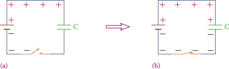
Figure 1 Capacitor charging instants (a) before and after (b) switch is closed.
When the voltage across the capacitor is the same as that of the power supply, the current is zero. The change in the current in the circuit containing the capacitor is shown in Figure 2. At the first instance, the connection is established the current has its maximum value.
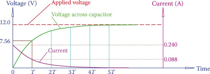
Figure 2 Current change in the circuit containing a charging capacitor.
The same argument is true when a charged capacitor discharges through a circuit. A current in the circuit flows and continues until the capacitor is fully discharged.
At the first instant, the capacitor is connected to the circuit, the current has its highest magnitude, which gradually decays to zero. Figure 3 shows the current change in a discharging capacitor. (The changing pattern is based on a decaying exponential curve.)
- Consider a circuit as shown in Figure 3a in which a capacitor is in a DC circuit with two resistors R1 and R2. When the switch is turned on and the resistors are powered, the capacitor charges and the voltage across it is the same as that of the battery.
- In Figure 3b the charge is shown as 1, which implies 100 percent of the battery voltage. Suppose now that at this time the switch is turned off. This instant is the beginning of discharge for the capacitor.
- The discharge takes place through the resistors R1 and R2, which form a closed loop with the capacitor. The voltage across the capacitor changes from the initial value to zero in a smooth way and depending on the time constant defined by C and resistors R1 and R2.
- In Figure 3b, T represents the time constant (as you remember, it takes approximately 5× the time constant for the circuit to settle to a new value after a change in the voltage has occurred).

Figure 3 Current change in the circuit containing a discharging capacitor. (a) The DC circuit containing a capacitor. (b) After the switch is turned off following being on, the discharge current starts from some value and decays to zero.
- You May Also Read: Inductors in AC Circuits
Capacitor Connected to AC Electricity
For a better understanding of what happens in an AC circuit containing a capacitor, we first assume a square wave AC signal. When the connection is made, the capacitor starts charging, but after it is charged (or before it is fully charged, depending on the capacitance), the half cycle terminates and the polarity changes.
The charged capacitor now must discharge and start charging in the opposite polarity. This process is shown in Figure 4. Because this charging and discharging happens continuously while the circuit is switched on, there is always some current flowing in the wires connecting the source to the capacitor, but not inside the capacitor. Thus, the circuit has a current, which can be measured.
Associated with this current, according to Ohm’s law, an ohmic value (that is measured in ohms) can be determined. The latter represents a current limiting entity, while it is not a resistance as in a resistor. It does not turn the electricity into heat.
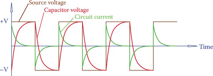
Figure 4 Current due to a capacitor in a circuit with a square wave voltage.
Similar to what happens with the inductors, the associated current limiting entity is called reactance, and because it stems from a capacitor, it is called capacitive reactance.
Capacitive reactance: Reactive effect of a capacitor when connected to AC electricity, measured in ohms. Capacitive reactance determines the current in a circuit containing a capacitor.
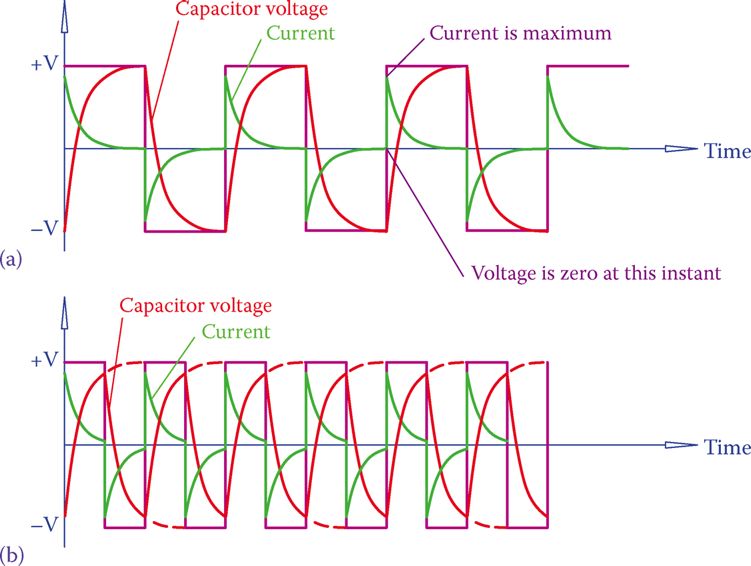
Figure 5 Effect of capacitance and frequency on the current in AC circuits with a capacitor. (a) Lower frequency: there is enough time for charging and discharging currents to fall to zero. (b) Higher frequency: there is not enough time for current during charging and discharging to become zero; result: more current in the case of higher frequency.
- Figure 5 shows two different possible cases for the current in a circuit with a square wave power source and a capacitor.
- In Figure 5a the capacitor is fully charged before it starts to discharge; in Figure 5b the capacitor does not get sufficient time to charge during a half cycle.
- In Figure 5a, by the end of each half cycle, the current has dropped to zero, while in Figure 5b the current has a nonzero value. We can say that the average magnitude of the current in Figure 5b is larger than the current in Figure 5a because there is less duration of zero value current.
- The difference between the current values is due to the capacitance of a capacitor. It can be seen that a larger capacitance leads to a larger current.
- Figure 5 also reflects the effect of frequency. The larger the frequency is, the less a capacitor has time to completely charge and discharge. Thus, the average current is larger because there are no or smaller periods of zero current.
- Figure 5 also shows that the maximum current (peak value of current) corresponds to the instance where the applied voltage is zero (the voltage changes sign; it passes through zero). This is more evident for a sinusoidal signal, as shown in Figure 6 because the changeover from charge to discharge (and this is when the current has its maximum absolute value) starts at the time the voltage changes sign.
Moreover, for the case of a pure capacitor connected to an AC source (sinusoidal waveform) the circuit current reaches its maximum (minimum) value at 90° before the applied voltage reaches its maximum (minimum). This is the opposite of the case for an inductor, as shown in Figure 6.
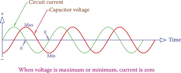
Figure 6 Current due to a capacitor in a sinusoidal wave AC circuit.
Current in AC Circuits Containing Capacitor
An observation of the current in Figure 5 reveals that the line frequency and the capacitance of a capacitor in an AC circuit have a direct effect on the magnitude of the current.
A larger capacitor (higher capacitance) takes more time to charge (or discharge), and a smaller capacitor takes less time to charge (or discharge). More time for charging and discharging implies higher current because current does drop to zero after charging.
A higher frequency implies smaller cycle time and, thus, less available time for charging and discharging.
Less available time implies that the current does not get sufficient time to reach zero; thus, more nonzero current (higher current). Therefore, the current in a circuit containing a capacitor is proportional to both the capacitor capacitance and the source frequency.
In consonance with what was said about an inductor in an AC circuit, the effect of a capacitor is exhibited by its capacitive reactance.
Capacitive reactance of a capacitor is determined from
\[\begin{matrix} {{X}_{C}}=\frac{1}{2\pi fC} & {} & \left( 1 \right) \\\end{matrix}\]
and is measured in ohms. In Equation 1, f is the line frequency in Hz and C is the capacitance in farads. It implies that as the frequency increases the value of XC decreases. Also, as C increases, the value of XC decreases (which implies a higher current). Thus, larger capacitors are leading to higher currents (for the same frequency), in consonance with what was said before.
When the frequency of an AC source connected to a circuit containing a capacitor increases, the capacitive reactance of the circuit decreases and circuit current increases.
Capacitor Current Calculation Example 1
What is the circuit current when a 12 V, 60 Hz electricity source is connected to a 51 μF capacitor?
Solution
Capacitive reactance is calculated from Equation 1 as
$\begin{align} & {{X}_{C}}=\frac{1}{2\pi fC}=\frac{1}{2\pi *60*0.000051}=52\Omega \\ & I=\frac{12}{52}=231mA \\\end{align}$
Capacitor Reactance Calcualtion Example 2
What is the reactance of the capacitor in Example 1 if it is connected to a signal with 10,000 Hz frequency?
Solution
Using the new value of frequency in Equation 1 gives
\[{{X}_{C}}=\frac{1}{2\pi fC}=\frac{1}{2\pi *10,000*0.000051}=0.321\Omega \]
From this example, you notice better a fact about capacitors in AC circuits. Whereas for 60 Hz frequency the reactance of a capacitor is 52 Ω, this value reduces to 0.3 Ω when the frequency is 10 KHz. For radio and TV signals that have a much higher frequency this value is almost zero. This means that a capacitor behaves like a solid connection.
At very high frequencies a capacitor behaves as a solid connection.
Capacitance Calculation Example 3
When a capacitor is connected to a 6 V, 50 Hz power source, the current is 500 mA. What is the capacitance of the capacitor?
Solution
$\begin{align} & XC=\frac{6}{0.5}=12\Omega \\ & \frac{1}{2\pi *50*C}=12 \\ & C=\frac{1}{2\pi *50*12}=265\mu F \\ \end{align}$
Capacitors in Series
Capacitors in series are shown in Figure 7. We need to find the one equivalent capacitor that replaces those in series. The rule for series capacitors is the opposite of the rule for resistors and inductors. For series capacitors,
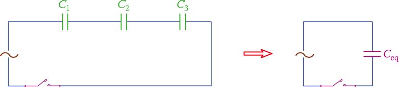
Figure 7 Capacitors in series.
\[\begin{matrix} \frac{1}{{{C}_{eq}}}=\frac{1}{{{C}_{1}}}+\frac{1}{{{C}_{2}}}+\frac{1}{{{C}_{3}}}+\cdots & {} & \left( 2 \right) \\\end{matrix}\]
If both sides of the above equation are multiplied by 1/2πf, then we get
\[\frac{1}{2\pi f{{C}_{eq}}}=\frac{1}{2\pi f{{C}_{1}}}+\frac{1}{2\pi f{{C}_{2}}}+\frac{1}{2\pi f{{C}_{3}}}+\cdots \]
Which is
\[\begin{matrix} {{X}_{eq}}={{X}_{1}}+{{X}_{2}}+{{X}_{3}}+\cdots & {} & \left( 3 \right) \\\end{matrix}\]
Thus, for finding the equivalent capacitor for series capacitors, Equation 2 must be used; however, if the reactance values are employed, they add together.
Capacitors in Series Example 4
In a previous repair job in a circuit, three capacitors had been put in series with each other instead or the damaged capacitor. If these capacitors are 47, 68, and 100 μF, find the value of the capacitor in the original circuit.
Solution
Using Equation 2, we find
\[\frac{1}{{{C}_{eq}}}=\frac{1}{47}+\frac{1}{68}+\frac{1}{100}=\frac{1}{21.74}\]
Thus, the original capacitor has been a 22 μF (the nearest standard value capacitor).
Capacitors in Parallel
We may need to put capacitors in parallel to obtain a capacitance value that cannot be found among standard capacitors. Capacitors in parallel are shown in Figure 8.
The rule for capacitors in parallel is easier. You add their capacitances together. That is,
$\begin{matrix} {{C}_{eq}}={{C}_{1}}+{{C}_{2}}+{{C}_{3}}+\cdots & {} & \left( 4 \right) \\\end{matrix}$
To find the equivalent reactance, however, they must be treated as resistors in parallel. This stems from multiplying the two sides of Equation 4 by 2πf. Thus,
$2\pi {{C}_{eq}}=2\pi {{C}_{1}}+2\pi {{C}_{2}}+2\pi {{C}_{3}}+\cdots $
Or
\[\begin{matrix} \frac{1}{{{X}_{C}}}=\frac{1}{{{X}_{C1}}}+\frac{1}{{{X}_{C2}}}+\frac{1}{{{X}_{C3}}}+\cdots & {} & \left( 5 \right) \\\end{matrix}\]
Capacitors in Parallel Example 5
A 33, 47, and 10 μF capacitor are put in parallel together. How much is the resulting capacitor?
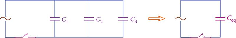
Figure 8 Capacitors in parallel.
Solution
It is sufficient just to add the three values together
$C=33+47+10=90\mu F$
Note that 90 μF can also be obtained from putting two standard 68 and 22 μF capacitors in parallel.
Capacitors in AC Circuits Key Takeaways
Understanding the behavior of capacitors in AC circuits is essential for the design and analysis of a wide range of electronic and electrical systems. Capacitive properties—such as charging and discharging behavior, capacitive reactance, and the effects of frequency and capacitance on current flow—are foundational to how capacitors regulate and manage current in AC signals. These principles are critical in real-world applications including filtering in power supplies, tuning in radio and television circuits, signal processing, and impedance matching in communication systems. By analyzing how capacitors respond to different frequencies and configurations, engineers can control current flow, improve energy efficiency, and ensure the proper functioning of sensitive electronic devices. The practical examples and calculations discussed highlight the direct impact these concepts have on designing effective and reliable AC circuits.