The article covers the analysis of AC resistive circuit, including the calculation of total resistance, current, and power, while explaining the relationship between voltage and current in these circuits. It also discusses various examples, including single-phase and three-phase resistive systems, and explores methods for measuring power in these circuits.
When an alternating voltage is applied to a circuit, it causes an alternating current of the same frequency to flow through the circuit. For purely resistive AC circuits the voltage and current are in phase with each other, as illustrated in Figure 1.
The voltage and current are considered to be in phase because the two waveforms pass through their zero values and increase in the same direction to their maximum values at the same time. Hence, the phase difference between waves that are in phase is zero.
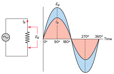
Figure 1 AC resistive circuit voltage and current waveforms.
For the most part, pure resistive circuits react much the same for AC or DC circuits. Resistive heating units and incandescent lighting are considered to be pure resistive loads. Resistive loads are characterized by the fact that they produce heat and the current and voltage are in phase with each other.
Theoretically, no AC circuit can contain only resistance. Other properties can affect voltage and current to a much lesser degree, allowing the circuit to be treated as being purely resistive.
In general, all the laws and formulas that apply to DC circuits also apply to AC circuits. Furthermore, they apply exactly the same way to AC resistive circuits. This is true, because resistors are linear components and their characteristics do not depend on frequency.
In a resistive DC circuit, both current and voltage are fixed, steady values. In an AC resistive circuit, the current alternates exactly in step with the voltage. The Ohm’s law formula for an AC circuit can be expressed as
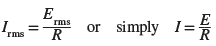
Unless otherwise stated, all AC voltage and current values are given as effective or rms values. With this in mind, the formula for Ohm’s law for an AC circuit can also be expressed as
When solving for quantities in AC-resistive circuits, the important thing to keep in mind is not to mix AC values. When you solve for effective values, all values you use in the formula must be effective values. Similarly, when you solve for peak or average values, all values you use must be peak or average values.
Total Resistance in AC Resistive Circuit Example 1
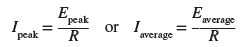
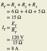
Problem: A series circuit consists of three resistors (R1 = 6 Ω, R2 = 4 Ω, and R3 = 5 Ω) and an alternating voltage source of 120 volts, as shown in Figure 2. Determine the total resistance of the circuit and the effective value of the current flow.
Figure 2 AC Resistive Circuit for example 1.
Solution:
In a DC circuit the power is equal to the voltage times the current ( P = E × I ) . This is also true in an AC circuit when the current and voltage are in phase; that is, when the circuit is resistive. With alternating current, the values of current and voltage vary with time. At any instant the power is equal to the current at that instant multiplied by the voltage at that instant.
Plotting all the instantaneous powers, as illustrated in Figure 3, produces a power waveform. Notice that the power waveform is always positive for in-phase currents and voltages. A negative current multiplied by a negative voltage yields a positive power. This means that the resistive load is converting electric energy into heat energy during the complete cycle. Then the power dissipated in a purely resistive load fed from an AC rms supply is the same as that for a resistor connected to a DC supply and is given as

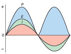
Figure 3 Power in an AC resistive circuit waveform.
Where I and E are the effective or rms current and voltage.
Total Power in AC Resistive Circuit Example 2
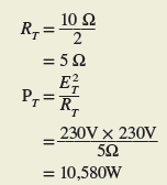
Problem: Find the effective total power consumed by the single-phase resistive circuit of Figure 4.
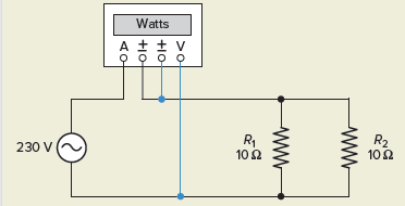
Figure 4 AC Resistive Circuit for example 2.
Solution:
For three-phase resistive circuits, voltages and currents are normally expressed as rms or effective values, as in single-phase analysis. The power in watts delivered to three-phase balanced resistive loads is calculated as follows:
Power is Resistive Circuit Example 3
Problem: Find the effective total power consumed by the balanced three-phase resistive heating load circuit of Figure 5.
Solution:
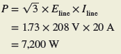
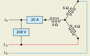
Figure 5 Three phase resistive load Circuit for example 3.
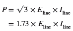
It is common practice to determine three-phase power in terms of the circuit’s line voltage and line current because it is generally easier to measure the line voltage and current in a three-phase system.
However, in a three-phase balanced resistive system, the total circuit power is also equal to the sum of the power of each of the three phases or three times the power of one phase:
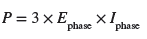
Figure 6 shows the connection of a single wattmeter used to measure the three-phase power of a balanced three-phase resistive load bank. Note that the wattmeter is connected to meter the phase current and voltage. Accordingly, three times the measured value of the wattmeter is equal to the three-phase power, as long as the three phases are balanced.
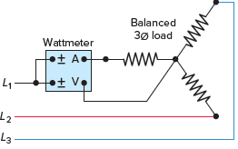
Figure 6 Single wattmeter used to measure the three-phase power.
Two wattmeters can be used to measure the three-phase power in systems which contain only three-phase conductors by metering the line current and voltage. Figure 7 shows the connection for the so-called two-wattmeter method of power measurement in three-phase systems.
If the three-phase system is balanced and resistive, then the two wattmeters will have the same readings, and the total circuit power will be equal to the sum of the two wattmeter readings W1 and W2. It is important to observe the polarity marks ( ± ) on the voltage and current coils of the wattmeters and make the connections exactly as shown.
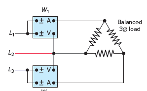
Figure 7 Two-wattmeter method of three-phase power measurement.
Review Questions
- What is the phase relationship between the voltage and current in an AC resistive circuit?
- What do all resistive-type loads convert electric energy into?
- An AC voltage of 340 V peak-to-peak is connected to a 10-ohm heater. Determine:
- The peak value of the voltage.
- The effective value of the voltage.
- The wattage of the heater.
- A series circuit consists of two 4-ohm resistors connected to a DC voltage source of 24 volts.
- Determine the total resistance and current flow.
- Repeat for the same circuit connected to a 24-volt AC source.
- A 240-VAC furnace heating unit consists of four 20-Ω heating elements connected in parallel. Determine the kW rating of the unit.
- The line voltage and current delivered to a balanced three-phase, wye-connected resistive load bank is measured and found to be 415 volts and 30 amperes, respectively.
- What is the value of the voltage across one phase of the load bank?
- What is the value of the current through one phase of the load bank?
- What is the value of the total kW power delivered to the load bank?
- If a single wattmeter is connected to meter the voltage and current of any one phase, what would its kW reading be?
- The line voltage and current delivered to a balanced three-phase, delta-connected resistive load bank is measured and found to be 480 volts and 104 amperes, respectively.
- What is the value of the total kW power delivered to the load bank?
- If the two-wattmeter method of power measurement is used, what would the kW reading of W1 and W2 be?
- Compare the voltages available from a four-wire 208 wye-connected system with that of a four-wire 480 wye-connected system.
- For the AC circuit of Figure 8 determine all values of voltage, current, resistance, and power. Record your answers in table form.
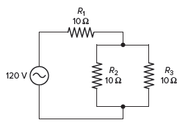
Figure 8 Circuit for review question 9.
10.Compare the method used to energize the magnetic field on the rotor of a synchronous AC generator with that of an induction type.
Review Questions – Answers
- The two are in phase with each other.
- They produce heat.
- (a) 170 V, (b) 120 V, (c) 1440 W
- (a) RT = 8 Ω, IT = 3 A, (b) RT = 8 Ω, IT = 3 A
- RT = 5Ω, PT = 11.52 kW
- (a) 240 V, (b) 30 A, (c) 21.6 kW, (d) 7.2 kW
- (a) PT = 86.6 kW, (b) W1 = W2 = 43.2 kW
- 208 V and 120 V or 480 V and 277 V
| Voltage | Current | Resistance | Power | |
| R1 | 80 V | 8 A | 10 Ω | 640 W |
| R2 | 40 V | 4 A | 10 Ω | 160 W |
| R3 | 40 V | 4 A | 10 Ω | 160 W |
| TOTAL | 120 V | 8 A | 15 Ω | 960 W |
10. The synchronous generator rotor magnetic field is created by using either permanent magnets mounted directly onto the rotor or electro-magnetically by an external DC current flowing in the rotor field windings. Induction generators receive field excitation from the power system to which the generator is connected.
AC Resistive Circuit Key Takeaways
The analysis of AC resistive circuits is crucial for understanding and applying electrical principles in various practical applications. By calculating total resistance, current, and power, and exploring the relationship between voltage and current, engineers and technicians can design and optimize circuits for different scenarios. The discussion of single-phase and three-phase resistive systems, along with methods for measuring power, is vital for industries such as power generation, electrical heating, and lighting systems, where resistive loads are commonly used.