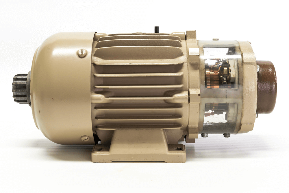
DC Motors and generators have the same basic construction and the typical machine can be used in both capacities.
For the DC motor to be useful it must develop torque, or a turning effect. When electrical energy is applied to a DC machine, current flows in the armature conductors and produces a magnetic field that interacts with the main magnetic field to cause a rotational torque to be developed (see Figure 1).
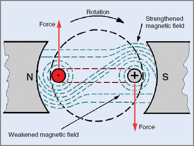
Figure 1 DC Motor effect produced by an electric current
When the two magnetic fields interact, an attractive force is created on one side of the conductors and a repulsive force is created on the other side. Remember that this is due to attractive force (axial) and the repulsive force (radial). The resulting magnetic field produces a force that acts on the conductors as indicated.
The direction in which the force acts can be determined by using the left hand (see Figure 2). This is done in a similar manner to that of the right-hand rule for obtaining the direction of an induced voltage in a conductor.
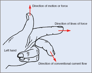
Figure 2 Fleming’s left-hand rule
Fleming’s Left-Hand Rule for Motors
| 1. | Arrange the thumb, first and center fingers of the left hand at right angles (90°) to each other. |
| 2. | Point the first finger in the direction in which the lines of force are acting. |
| 3. | Point the center finger in the direction in which the current is flowing. |
| 4. | The thumb will then point in the direction in which the force is acting on the conductor |
The left-hand conductor in Figure 1 has a tendency to be forced upwards and the right-hand conductor downwards. As these are normally imbedded in an armature core at a fixed distance from the center of rotation, the effect is to create a turning movement, or torque.
In a practical DC motor there is a large number of conductors and the torque produced is sufficient to drive the load connected to the motor, unless the motor is severely overloaded.
There are more DC motors in use than DC generators because one generator in an installation can supply several motors. The type of generator often used is the compound type, the motors themselves having varying connections depending on the job in hand.
The suitability of a motor connection for any specific purpose will depend on the torque developed and the difference in speed as the load is altered.
The most common characteristic curves of DC motors are concerned with speed and torque as a load is applied, whereas generator curves show output voltage plotted against load.
Commutation and armature reaction are applicable in their entirety to motors as well as generators, with the possible exception of the direction of magnetic neutral plane shift.
Torque
The magnitude of the thrust exerted on a conductor carrying a current when located in a magnetic field is given by the equation:
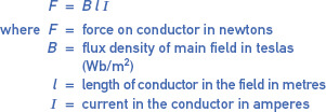
In a practical case, where an armature has many conductors and also may have several paths, the equation becomes:

Since T = Fr where r is the radius of rotation of the armature conductors, the equation becomes:
![]()
The formula can be further developed to:
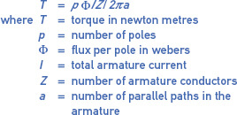
DC Motor Torque Calculation Example 1
A four-pole DC motor has a lap-wound armature of 30 coils, each with 20 conductors. If the flux per pole is 0.02 Wb and the armature current is 19 A, calculate the torque produced.
![]()
Points to note when considering a motor in these terms are:
| 1. | In Example 1 where each coil has 20 conductors, the coil has only ten turns because each coil side acts separately. |
| 2. | The output power (P = 2πnT) can also be related to the above formula for calculation of torque, provided the speed is known. |
| 3. | This in turn can be related to input power from the supply source. A measurement of input power (P = VI) can be used to determine efficiency. |
DC Motor Output Power Calculation Example 2
If the DC motor in Example 1 above is rotating at 1100 rpm, find the output power.

Permanent-Magnet Motors
The most common DC motor of any type is the permanent magnet electric motor. In this motor, the field has no winding but consists of a permanent magnet. A common everyday use for the permanent-magnet motor is in small applications such as the vibrating motor in mobile phones, electronic tape recorders and players, CD players, toys, radio-controlled aero planes and boats.
This category of both motors and generators was once reserved for smaller machines but the present stage of development in permanent magnets allows the construction of much larger motors with permanent-magnet fields.
Because they have no wound field, there is a growing tendency to a reduced unit cost and an increase in efficiency. Motors up to approximately 7.5 kW use ceramic magnets. While highly resistant to demagnetizing, they have a relatively low flux level and are therefore limited in application and size.
For larger DC motors, alnico magnets are used and the motor is easily adaptable to extreme applications such as steel mill service (e.g. furnace electrode drives, live table drives).
Normally the magnet is molded and set in the motor frame and used for low-speed applications (e.g. machine tools). The magnets can be seen in Figure 3. These magnets have been fixed in position by a high temperature bonding agent.
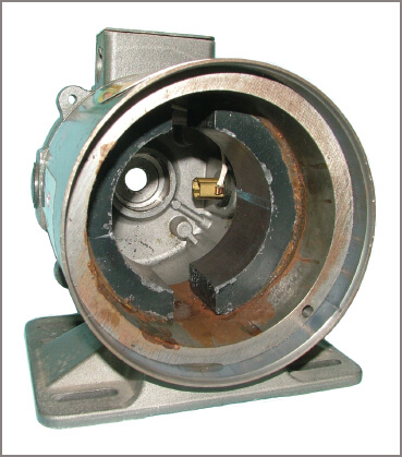
Figure 3 View of the alnico magnets of a permanent-magnet DC motor
Speed control is traditionally achieved by varying the voltage applied to the armature. Modern electronics has made this method of speed control very effective and efficient. Torque is comparatively linear throughout the normal load range. Figure 4 shows characteristic curves for a permanent-magnet motor.
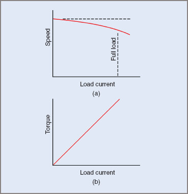
Figure 4 Characteristics for a permanent-magnet DC motor
Printed Circuit Motors
Printed circuit motors are a variation in construction of the permanent-magnet motor. The armature itself has no iron in its construction and is consequently an air-cored armature. Figure 5 shows the construction of the motor in its simplest form. Several circular magnets are fastened to a casting that forms the basis of field support and motor end-shield in one piece.
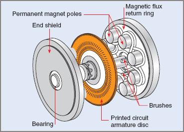
Figure 5 General construction features of a printed circuit motor
The motor end has provisions to mount a bearing so that the armature can be maintained in its correct position within the air gap. The second end-shield consists of magnetic material to concentrate the magnetic paths within the motor and provides brush and bearing mounting facilities.
For increased torque, motors may have a set of magnets each side of the armature and the material used then in end-shield construction may be non-magnetic.
The armature coils are created by an etching process on a non-conducting substrate. Often of Bakelite or fiberglass, the base material is initially coated with a film of pure copper deposited on it by an electroplating process and may be single- or double-sided.
Where an armature coil might need to consist of more than one turn, double-sided material may be used. The conductor shapes are outlined on the copper and the material in between is removed by photo-etching.
Printed circuit motors are lightweight, with a short shaft length, run at low speed and low voltage. Output torque is limited because of armature construction using no iron and efficiency is low. Commutation problems are never encountered because of low coil inductance.
Separately Excited Motors
The wound-field separately excited DC motor has no limitations in size, like the permanent-magnet variety. Like the separately excited generator, the motor is used mainly in process control work. This type of field connection is adaptable to a wide range of speed control and the torque is also linear with respect to the applied load. See Figure 6 for the circuit of the wound-field type.
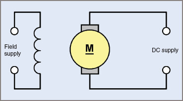
Figure 6 Circuit Diagram for a separately excited wound-field DC motor
Because the machine has similar characteristics to the permanent-magnet motor, its uses are also similar. It has the advantage of being used in other circuits, such as Ward-Leonard control systems, gun-platform leveling and rotary amplifiers, where a small change in field current can be made to cause a large change in speed.
A special construction of the separately excited wound-field motor makes it suitable for positioning work, as in long-distance readings of anemometers and engine speed governors.
The normal or rated speed of a separately excited DC motor is obtained with rated voltage applied to both the field and the armature. This speed is termed the base speed of the motor. If the voltage applied to the armature is reduced the motor will slow down. So for speeds below base speed, armature voltage control is used.
If the voltage applied to the field is reduced, with rated voltage on the armature, the motor speed will increase. This method is called field weakening and is used to give speeds above base speed.
Under normal circumstances the field-current control method is preferred, owing to lower currents in the control device, giving less electrical power wastage. However, modern electronic methods of armature voltage control are very efficient.
When a motor armature rotates in its magnetic field, a voltage is generated that opposes the applied voltage. The current flowing in the armature is, based on Ohm’s law, proportional to the difference in these two voltages divided by the armature resistance.
If a rheostat is connected in series with the field, any reduction in resistance results in an increase in field current and in turn an increased field strength. At a constant armature speed, an increase in field strength leads to an increased generated voltage (back EMF), which tends to reduce the armature current, and the motor therefore produces less torque. As a consequence the motor slows down as the armature current increases and the motor stabilizes at a lower speed.
Conversely, a decrease in field current leads to an increase in speed. Therefore, precautions must be taken to ensure that the field current does not decrease below a certain level that permits excess armature currents and dangerous speeds to result.
DC Motor Reversal
DC Motor reversal is achieved by altering the polarity of the supply to either the field or the armature. The basic principle of reversal of rotation for a DC motor requires that the direction of current flow through either the field or the armature windings be reversed, but not both.
Reversing the polarity of both supplies results in no change in rotation, as the direction of current flow in both the armature and field windings is reversed.
Figure 7 illustrates one method of reversal of rotation. In both diagrams the field polarity is unchanged, while the direction of current flow through the armature is changed (see Figure 7(b)). The torque created is equal in both cases, but the resultant direction of rotation has changed.
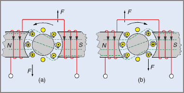
Figure 7 Reversal of rotation of a DC motor
DC Shunt Motors
The shunt-field connection is commonly used in the smaller size range. In larger sized DC motors the shunt connection is found less frequently, but is still used because of its fairly constant speed characteristic. Of the several types of motor connections, the shunt-excited motor has the best speed regulation throughout the normal speed range.
Like the shunt generator, the shunt-field of the motor is connected in parallel with the armature and the motor speed can be controlled by a series resistor, regulating the current flow through the field. The basic motor circuit is shown in Figure 8, together with the characteristic curves for speed and torque.
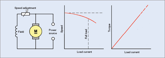
Figure 8 Shunt DC motor characteristics
Under normal operating conditions the speed of the motor is set with the field rheostat. Decreasing the resistance value increases the field current, and causes the same sequence of events with speed adjustment for the separately excited machine. Below normal speed operating ranges, the voltage to the armature is varied with a series armature resistor to give speed variations.
In a similar fashion to the separate-field motor, precautions must be taken to ensure that the field current is never reduced below a certain value in order to prevent excessive armature speeds and current.
Reversal of rotation is by the same method as the separate-field machine in that either the armature or the field current flow is reversed, but not both.
DC Series Motors
In series-field DC motors, the field and armature are in series with the supply in a circuit similar to the series generator. The circuit and characteristics are shown in Figure 9. The series motor is subject to wide changes in speed as its load is varied, because of the changing field current. With a series motor on full load, both the armature and field current are at comparatively high values.
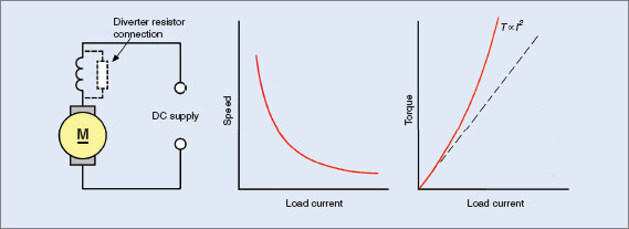
Figure 9 DC Series motor characteristics
Under Separately Excited Motors section above, it was discussed in some detail how increasing the field current of a motor reduced the speed and, conversely, decreasing the field current increased its speed. Thus with full load (and field) current, the speed of a series motor is low; and, as the mechanical load is removed from the motor, the armature current (also the field current) is reduced. When the magnetic field becomes weaker, the motor speeds up.
With larger sized series motors, speeds can be attained under no-load conditions that are sufficiently high to cause damage to the motor. A normal precaution is to have a minimum load permanently connected by direct coupling or similar means to prevent the possibility of removing all of the mechanical load.
The torque characteristic of a DC series motor is non-linear because as the load applied to the motor increases and the motor slows down both armature and field current increase together.
Torque can be stated as:
\[T={}^{p\phi IZ}/{}_{2\pi a}\]
For any one machine, the number of poles p, the number of conductors Z, the number of parallel paths a and the value of 2π will remain constant, so the formula can be written in the form T ∝ ΦI. Since Φ, the field flux, is proportional to the armature (field) current, T ∝ I2 for a series motor.
Inspection of the characteristic curves shows that an armature current increase is associated with a decrease in speed and an increase in torque. These factors show the big advantage and common use of the DC series motor: starting against heavy loads.
Typical uses are traction motors in electric trains, cranes, anchor winches, elevators and, the most common task, as the starter motors for motor cars.
To reverse the direction of rotation, reverse either the field or armature leads, but not both.
Speed control methods are not really applicable to series motors because of their inherent wide range of speeds, but at any one load and voltage the speed can be increased with the use of a diverter resistance to bypass some of the armature current around the field.
DC Compound Motors
In the cumulatively compounded connection, the series and shunt windings assist one another, thereby increasing magnetic field strength. This is the connection normally used.
As with compound generators, compounding can be under-compounded, level-compounded, over-compounded or differentially compounded.
Differential compounding is possible but has little practical use. If a differentially compounded motor is loaded beyond a certain point its current increases rapidly and the motor abruptly changes its direction of rotation. This can create a dangerous situation as, depending on size and torque of the motor, a sudden reversal can cause damage to couplings and gearboxes or even twist off a motor shaft.
The cumulatively compounded motor combines the characteristics of both the series and shunt motors. Its speed regulation is not as good as in the shunt motor, but is superior to the series motor. While the torque of the shunt motor is approximately linear, the torque of the compound motor increases more rapidly, but at the cost of some loss in speed. Its torque, however, is less than that of the series motor.
The compound motor is the general workhorse among DC motors and is especially suitable to loads that require a reasonably high degree of starting torque but which do not require a series motor. The shunt winding allows the motor to run at very light loads, a factor that gives it an advantage over the series motor.
Applications include punches, shears, rolling mills, and drive motors for machines subject to sudden or shock loads and reversals such as large metal planning machines. Characteristics of the compound motor are shown in Figure 10.
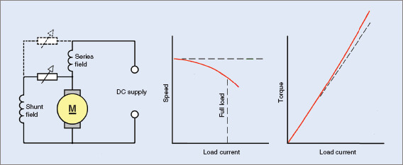
Figure 10 DC Compound motor characteristics
It should be noted that with large traction loads, such as diesel electric drives in ships and particularly diesel electric locomotives with multiple bogie drives, the basic drive motor is referred to as a series motor.
In fact it is probably a compound motor with the shunt field open-circuited during starting. Several series motors may also be connected in series with one another. As the load becomes mobile, it is normal practice to reconnect the series motors in parallel and still later to convert the series motor connection to a shunt or a cumulative compound type.
While it can be said that a series motor (or a shunt motor) is applicable to some particular job, it should be appreciated that the one motor can be electrically reconnected while still rotating, to suit conditions that have changed since the motor started.
Similarly a DC motor in motion can be reconnected to behave as a generator supplying a resistive load and to form part of a braking sequence to reduce wear on brake shoes (e.g. in an electric train travelling downhill).
One form of emergency braking for electric trains is to reverse the electric motors and apply full voltage. When reversing the cumulatively compounded motor, it must be remembered that there are two field windings. As is often the case the machine might have interpoles as well and the reversing situation has to be handled more carefully. Both the shunt and series windings have to be reversed together, but not the armature or the interpoles.
Reversing either the shunt or series windings on their own merely changes the machine’s connection from cumulative to differential compounding. Figure 11 summarizes the characteristics of DC motors.
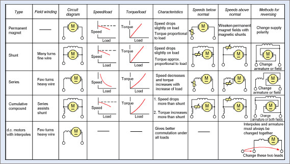
Figure 11 Comparison of the characteristics of DC motors
Voltage Generated In a DC Motor
When a voltage is applied to a motor at standstill, the current that flows will be governed by the resistance of the motor and the initial or starting current can be quite large unless steps are taken to prevent it. Typically a 200 V compound motor of 3.5 kW could have an armature resistance of approximately 0.5 Ω.
![]()
Under everyday operating conditions this Figure is far in excess of the usual current a motor of this size would draw, so other factors must be involved. There are three factors necessary to produce an EMF. They are a conductor, a magnetic field and relative motion between the first two. With an electric motor at standstill the relative motion does not exist.
The relative motion component does exist however, as the instant the motor starts rotating an EMF is generated. From Lenz’s law the induced EMF opposes the applied voltage and the effective voltage causing current to flow in the motor is the difference between these two voltages (see Figure 12).
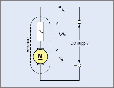
Figure 12 Generated voltage in a DC armature
The generated voltage, usually called back EMF or counter EMF, is always assumed to occur only in the armature.
For a motor field:

For the armature:
![]()
Transposing:

DC Motor Back EMF Calculation Example 3
A 500 V DC motor draws an armature current of 540 A on full load. Find the value of the back EMF if the armature resistance is 0.002 Ω.

Speed Regulation
Speed regulation for a motor expressed as a percentage is found from:

The smaller the value of percentage regulation, the less speed the motor loses on load.
Regulation values of 5 or 6 per cent indicate good speed regulation, where there is little speed loss from no load to full load; 100 per cent regulation is very poor and means the motor stops altogether when placed on load.
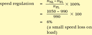
Example 4
A shunt-connected DC motor runs at 1050 rpm on no load and slows to 990 rpm on full load.
Calculate the speed regulation.
You May Also Read: DC Generator Types & Working
