The article discusses harmonic distortion in inverters, explaining how non-sinusoidal waveforms contain harmonic frequencies that distort pure sine waves. It also covers methods for generating and filtering waveforms, including the use of modified square waves and filters to produce clean sine wave outputs.
It has been found that any periodic (repeating), the non-sinusoidal waveform can be produced by adding a series of sine waves at frequencies other than the fundamental. The fundamental frequency of a waveform is also called the first harmonic.
AC voltage and current waveforms consist of frequencies, called harmonics that are multiples of the fundamental frequency. For example, if a waveform has a fundamental frequency of 5 kHz, then multiples are 10 kHz, 15 kHz, 20 kHz, and so on, and these harmonics could be contained in the waveform.
A pure sine wave consists of only the fundamental frequency and is free from other harmonics, but non-sinusoidal waveforms consist of the sine wave fundamental frequency and harmonics. A 5 kHz square wave, for example, consists of the 5 kHz fundamental and other odd harmonics such as 15 kHz, 25 kHz, and 35 kHz.
A 50Hz square wave consists of a series of sine waves added together: first 5 50Hz, third 5 150Hz, fifth 5 250Hz, and so on. A square wave contains only odd harmonics, but some waveforms contain even harmonics or both even and odd harmonics.
Even harmonics are even multiples of the fundamental; if a certain type of 2 kHz waveform consists of even harmonics, then it consists of the fundamental and harmonics of 4 kHz, 8 kHz, 12 kHz, and so on. A waveform with the fundamental and second harmonic is illustrated in Figure 1.
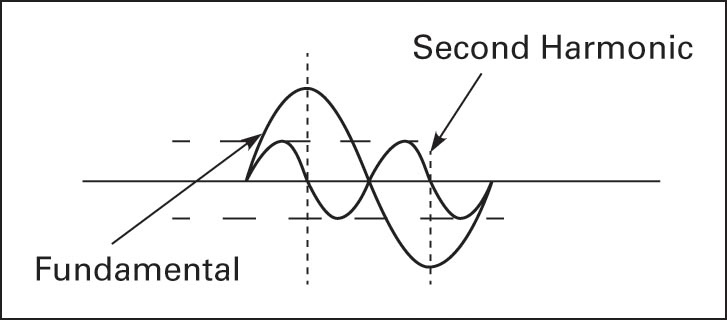
Figure 1 The second harmonic is twice the frequency of the fundamental
A pure sine wave generator can have harmonics introduced back into the sine wave by driving loads that draw current in pulses such as fluorescent light ballasts, computers, and motor controllers. If a sine wave has odd harmonics added back into it, then the sine wave will be distorted (see Figure 2) and start to look like a square wave.
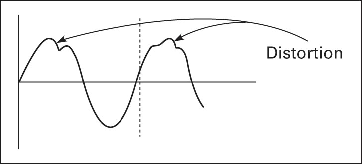
Figure 2 Sine wave distorted by harmonics
If a sine wave is produced using pulse width modulation techniques, then high-frequency sine wave harmonics are introduced into the waveform and must be eliminated before supplying a pure sine wave voltage to the grid.
High-quality grid-tied inverters have a total harmonic distortion (THD) of less than 5%. The THD of a waveform is calculated as the sum of the power of each harmonic, other than the fundamental, divided by the power of the fundamental. As an example, a square wave has only odd harmonics, and the THD is calculated as
\[THD=\frac{\left( {{P}_{3}}+{{P}_{5}}+{{P}_{7}}+\cdots +{{P}_{n}} \right)}{{{P}_{1}}}\]
Where Pn is the last harmonic used in the calculation, P1 is fundamental, P3 is the third harmonic, and so on.
Harmonics cause overheating problems on power lines, connecting wires, motors, and transformers. They can cause protective devices to trip intermittently and reduce the power factor. Static noise in audio systems is often a result of harmonics in the signal.
- You May Also Read: Inverter Types and Applications
Harmonics are eliminated by using filters. The term sine wave inverter does not indicate a “pure” sine wave. A typical high-quality sine wave inverter has a THD of less than 5%.
Generating a Modified Square Wave
Figure 3 is a basic modified square wave inverter. Q1 and Q2 are MOSFET semiconductor switches. MOSFETs have higher input impedance than standard bipolar transistors and therefore use hundreds of times less power.
The positive terminal of the DC source is connected to the transformer center tap (C.T.). The control module is programmed to control the switching of Q1 and Q2.
By switching on Q1, source current flows through Q1 to C.T. of the primary and returns to the source. The control module then switches on Q2 (switching off Q1), and source current flows through Q2 to C.T. of the primary and returns to the source. By alternating the switching on and off of Q1 and Q2, a magnetic field is induced into the transformer secondary, producing an AC output voltage.
Because Q1 and Q2 are only switched on and off, the output, after filtering, does not produce a sine wave, but the device can be controlled to generate a square wave or a modified square wave by a control algorithm that adjusts the spacing between pulses (Figure 4).
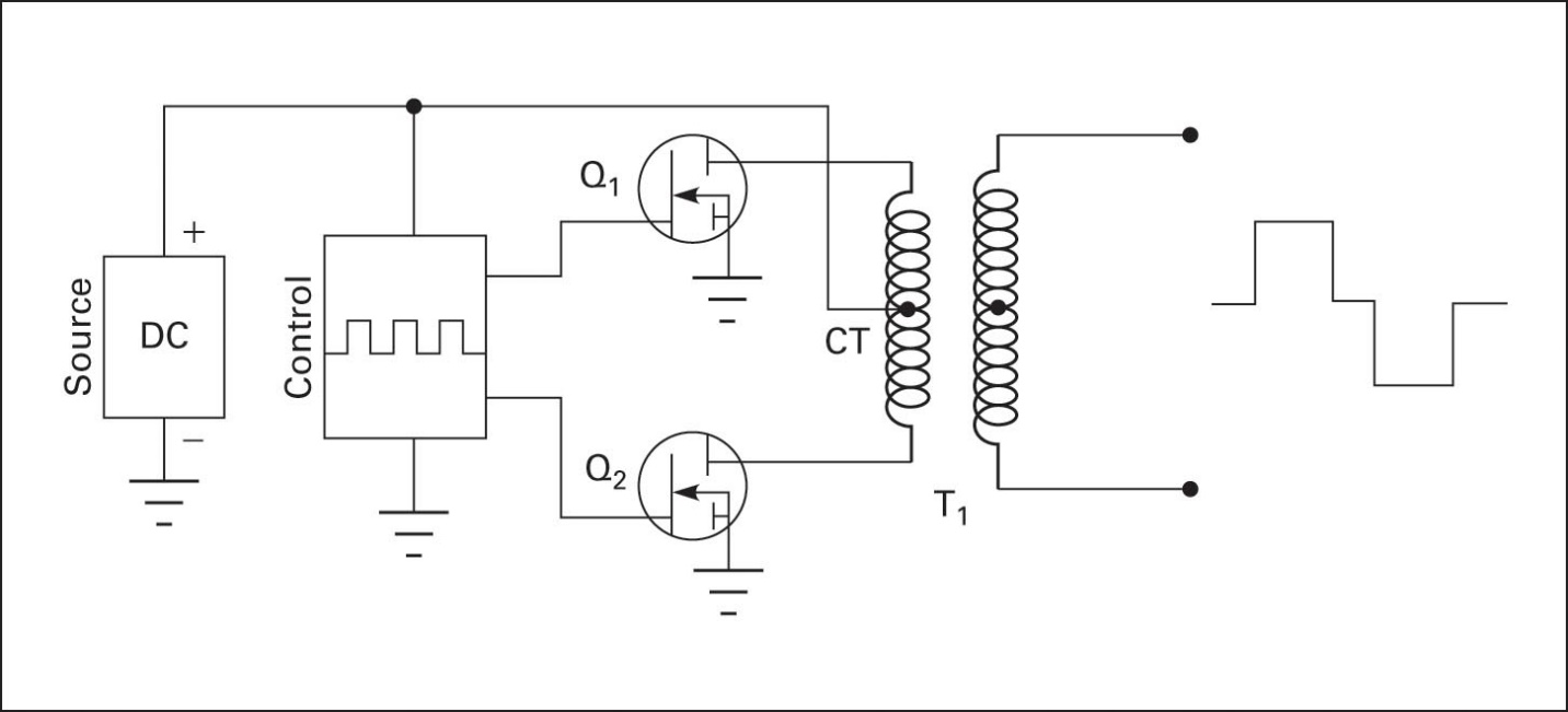
Figure 3 Circuit to generate a modified square wave
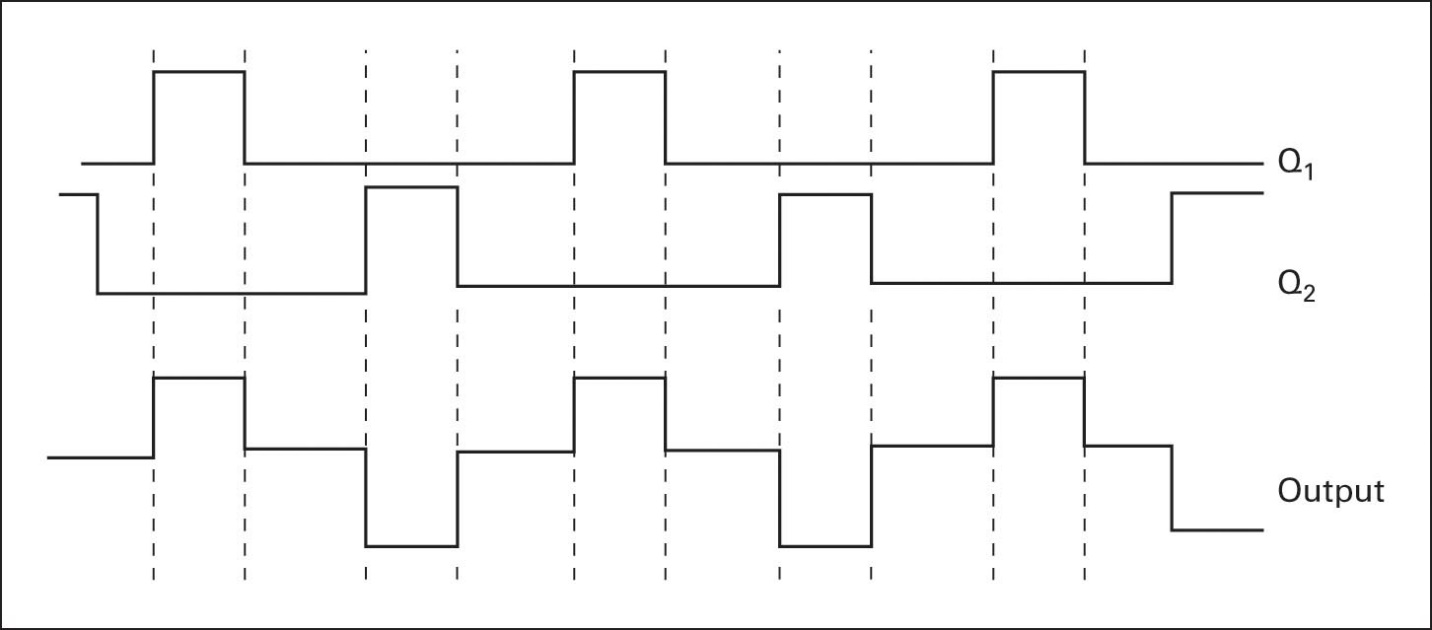
Figure 4 Control timing to generate a modified square wave (see Figure 3)
Generating a Sine Wave
Assume an AC square wave consists of the first (fundamental), third, fifth, and additional odd harmonics. Figure 5 illustrates a square wave with the fundamental sine wave component and the third and fifth harmonics.
If the fundamental sine wave is 60Hz, then the third harmonic is 180Hz and the fifth is 300Hz. These harmonics can be extracted from the fundamental using filters.
A filter is a network of resistors, inductors, and capacitors that are used to block certain frequencies but allow other frequencies to pass to a load.
Figure 6 shows the fundamental, the 60Hz sine wave, passing through a filter and the higher harmonics being blocked. A low pass filter designed to allow 60Hz to pass will filter out frequencies above 60Hz.
A pure sine wave can be produced by generating a high-quality square wave and then filtering out the harmonics, leaving only the fundamental.
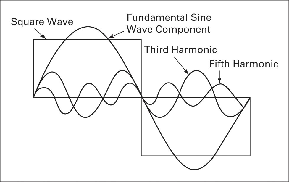
Figure 5 Square wave with sine wave harmonics
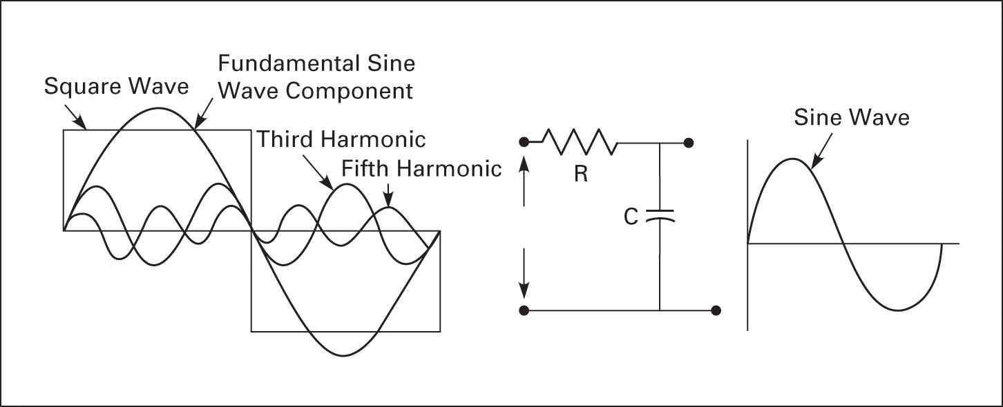
Figure 6 Filtering out third and fifth harmonics
Inverter Harmonic Distortion Key Takeaways
Understanding and managing harmonic distortion is crucial for the efficient and reliable operation of electrical systems, particularly in inverter applications. Harmonics can significantly impact the performance of connected equipment by causing overheating, reducing power factor, creating unwanted noise, and potentially damaging sensitive electronics. In power systems, especially those supplying clean energy to the grid, maintaining a low total harmonic distortion (THD) ensures compliance with industry standards and enhances the lifespan of electrical components.