The article provides an overview of inverters in renewable energy systems, focusing on their role in converting DC to AC, their efficiency, and output waveforms. It also discusses photovoltaic (PV) cell characteristics, maximum power point tracking (MPPT), and the impact of environmental conditions on inverter performance.
In many cases, renewable energy sources have DC outputs. The outputs of PV cells, fuel cells, some wind turbine generators, and other renewable energy devices are DC, but most of the world uses AC power. Therefore, DC power sources use an inverter to change DC to AC.
Early inverters were rotary motor–generators, connected by a shaft, and they mechanically converted/inverted DC to AC. Modern inverters are electronic devices that use semiconductors to change DC to AC. An AC inverter is a high-tech microprocessor-controlled device and is a key element in many renewable energy systems.
Characteristics of a PV Cell
To understand the functions of inverters and maximum power point trackers in the context of photovoltaics, an understanding of the characteristics of a PV cell is necessary.
A PV cell is a constant current and variable voltage device, whereas a power utility rotating electrical- mechanical generator is a constant voltage and variable current device. For example, utility power connected to a house is usually constant at 120 volts, and the current varies depending on the load.
A constant current generator is an opposite: the current is constant, and the voltage varies depending on the load. This characteristic of a PV cell is represented by a curve of current versus voltage, called the I-V curve. The I-V curve represents all possible voltage and current operating points for a specific set of conditions.
Figure 1 illustrates two I-V curves, the first at a solar intensity of 1000 watts per square meter and the second at a solar intensity of 800 watts per square meter. Each curve is at a temperature of 25°C.
The maximum power point for each curve is indicated as MPP and represents the value of current and voltage for that set of operating conditions that will transfer maximum power to a load (P = I * V). Observe that the MPP for each curve is located at the knee of its I-V curve.
For a specific solar intensity and temperature, each curve illustrates that the current is approximately constant until just past the knee and after the knee, it rapidly drops to zero.
Figure 2 illustrates the effects of temperature on the I-V curve for silicon PV cells. The first curve is at 25°C and the second curve is at 85°C. Observe that, as temperature decreases (gets colder), voltage increases and that, as temperature increases (gets warmer), the voltage decreases. The current remains approximately constant with changes in temperature.
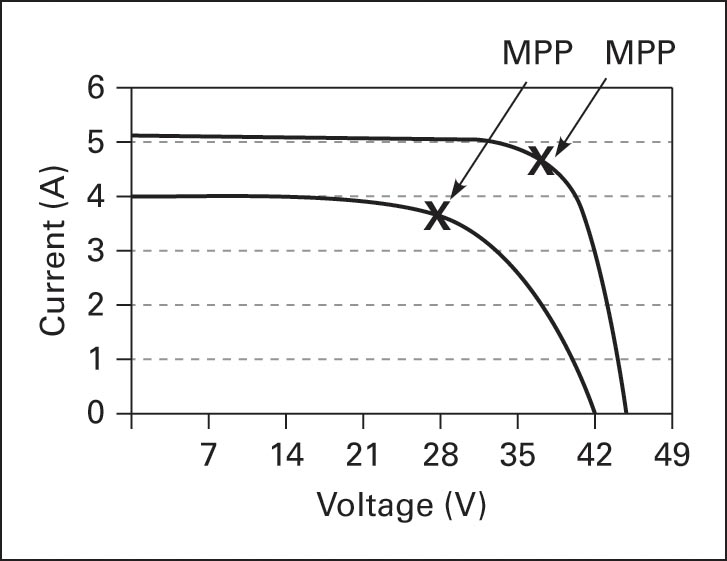
Figure 1 PV module characteristic curves with changing the solar intensity
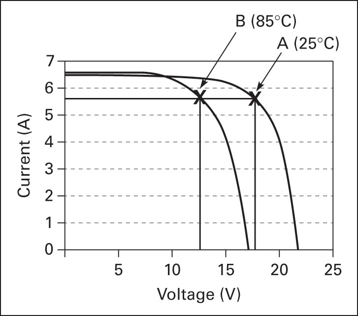
Figure 2 PV module characteristic curves with changing the temperature
When cell voltage increases beyond the MPP, the cell current decreases rapidly with a corresponding decrease in power. An inverter must respond to these changes and supply power to the load at the required current and voltage, and it must disconnect from the load when the requirements cannot be maintained.
Inverter Working
An inverter is an electrical device that converts direct current to alternating current. Inverters are used in PV systems to change the DC array output to AC at a constant voltage and frequency.
Also, the output power of a wind turbine may be AC or DC, depending on the type of generator, and if DC, then an inverter is used for DC to AC inversion.
Many inverters have two functions: (1) to change DC voltage to AC voltage and (2) to extract maximum available power from the PV module using maximum power point tracking.
- You May Also Read: Inverter Functions & Applications
Figures 1 and 2 indicate changes in cell voltage, current, and power caused by the solar intensity and temperature changes. These changes shift the maximum power point, and to maintain maximum power transfer from the source to the load, the inverter must adjust the source load to operate at the source MPP, therefore extracting maximum available power. The function of adjusting load is called maximum power point tracking (MPPT).
Inverters are designed to be grid independent, meaning they operate without a grid connection, or to be grid interactive. When operating grid interactive, if the grid is available, the inverter can receive power from the grid or supply power to the grid.
A power inverter controls voltage and current between the source (PV array, wind turbine, or other types of DC source) and the electrical loads and converts variable DC output into a quality sinusoidal waveform. PV cell efficiencies and inverter efficiencies are both keys to the success of PV renewable energy systems.
Figure 3 shows a solar array feeding DC to an inverter and AC is then supplied to a building. Figure 4 illustrates an application where variable AC from a wind generator is rectified to a more constant DC and then inverted back to a constant AC. The utility grid and local loads must be supplied with a constant voltage AC waveform.
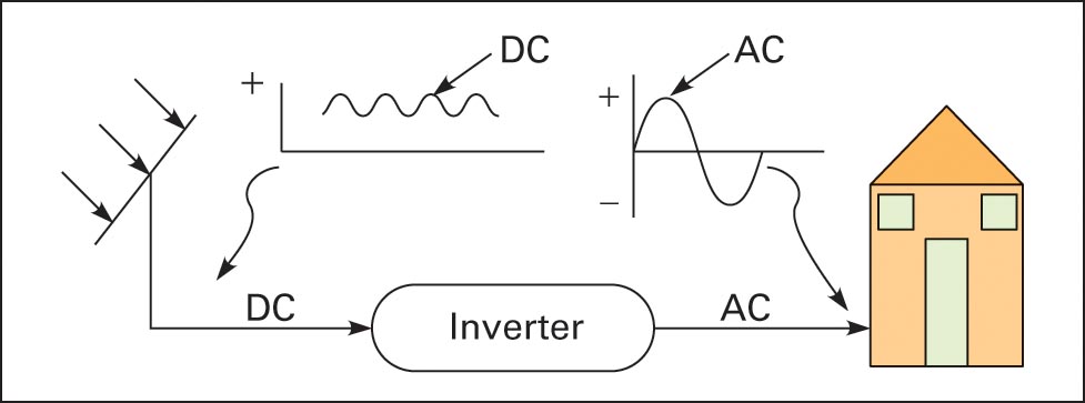
Figure 3 PV array DC-to-AC inversion
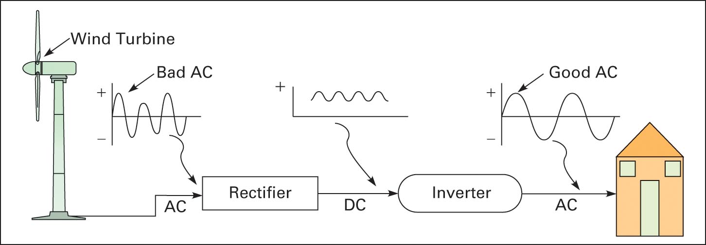
Figure 4 Wind turbine AC-to-DC-to-AC conversion
Most electrical power in the United States and the world is alternating current (AC). An advantage of AC is that it can be transformed into a high voltage using a transformer, and therefore current is reduced. Lower current reduces voltage drop and power loss on transmission lines and connecting wires.
The inverter AC voltage can be transformed and connected to the utility grid or fed directly to homes and commercial AC loads where the system is installed.
Figure 5a illustrates AC waveforms that can be transformed because they switch from positive to negative, but the DC waveforms in Figure 5b cannot be transformed. For transformer action to occur between primary and secondary windings, the input voltage must change polarity periodically, and this is not the case in Figure 5b.
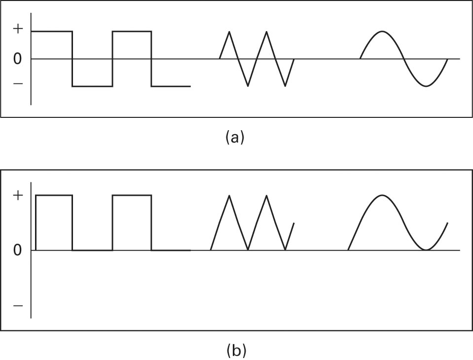
Figure 5 (a) AC and (b) DC waveforms
Inverter Output Waveforms
Figure 6 illustrates inverter output waveforms after DC-to-AC conversion. Square waves are non-sinusoidal and are the easiest for an inverter to produce.
Square waves can be used for driving certain resistive loads such as resistive heaters and incandescent lights, but a square wave contains high harmonic content and harmonics cause waveform distortion, overheating of wires and motors, a low power factor, and poor power efficiency.
Square waves are not used to supply power to computers and electronic equipment, and they cannot be used to supply power to the utility grid. In general, they have very limited applications.
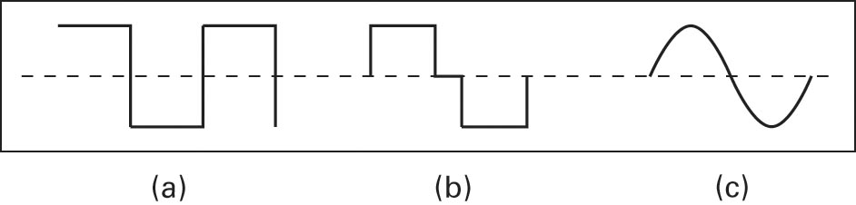
Figure 6 Inverter output waveforms after DC-to-AC inversion: (a) square wave; (b) modified square wave; and (c) sine wave
Modified square waves more closely resemble a sine wave, but they are non- sinusoidal. Harmonic distortion, efficiency, and voltage regulation are improved compared to the square wave.
Modified square waves are used in certain stand-alone applications, but before using a modified square wave inverter, consult with the manufacturer with regard to the application.
In the United States, a modified square wave inverter is not approved for interactive (grid-tied) applications because the AC isn’t of utility-grid quality.
Utility-grade sine wave inverters provide high-quality AC power with low harmonic distortion, a high power factor, and grid synchronization and are considered a pure sine wave source equivalent to the rotating generators used by the utility grid.
Utilities use rotating AC generators that are designed to be grid compatible and produce a quality sine wave. Sine wave inverters that meet appropriate certifications can be used for grid-interactive applications. Grid-tied inverters are called utility-interactive inverters and meet high utility standards.
They have a total harmonic distortion of less than 5%, disconnect from the grid when power is lost, and reconnect when grid power is restored. Grid-tied inverters have excellent voltage and frequency regulation and a high power factor, and they synchronize phase and frequency to the utility grid power.
Small AC and DC generators (see, for example, Figure 7) are driven by wind turbines. The DC output of these machines supplies inverters connected to the grid. Wind turbines and PV systems can operate together as a hybrid system.
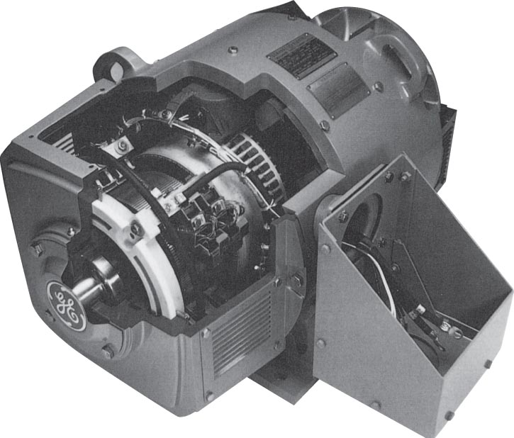
Figure 7 Small DC generator
Nameplate information is used to find maximum continuous AC output current, which is determined by the maximum power rating and minimum AC voltage (see Figure 8a).
IAC @ 208V = P/V = 5000/208 = 24A
Maximum continuous DC input current is determined by the maximum power rating and minimum DC voltage.
IDC @ 250V = P/V = 5000/250 = 20A
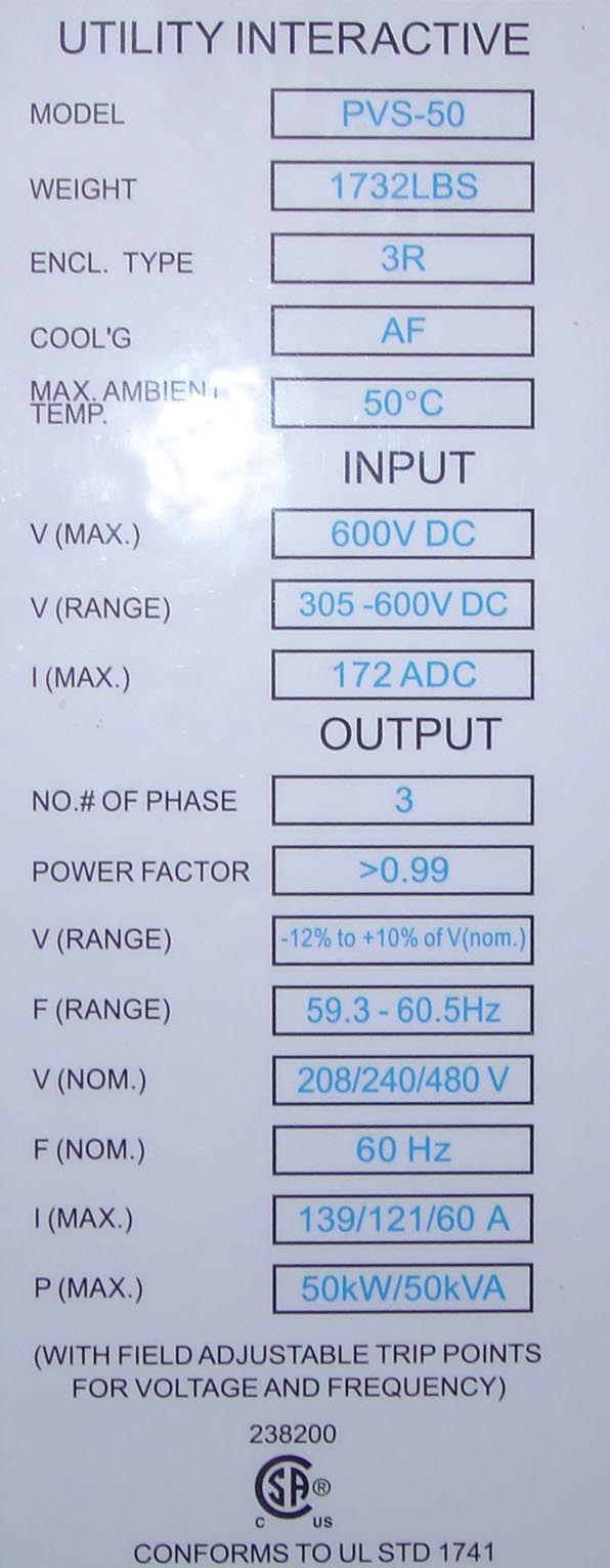
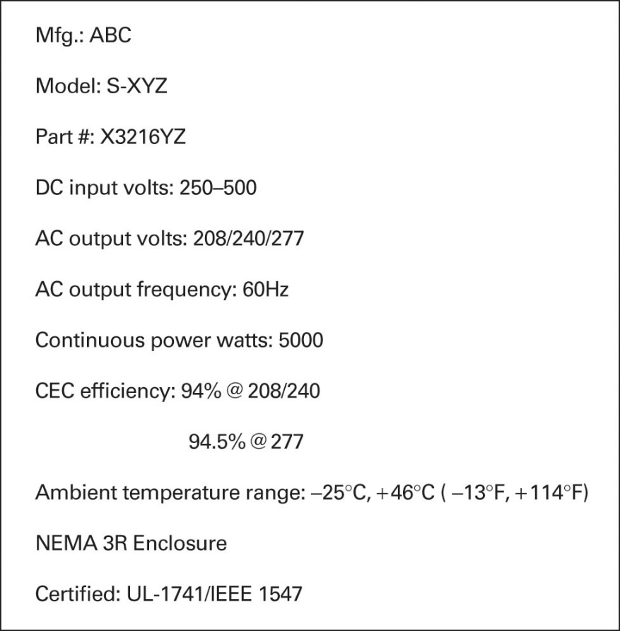
Figure 8 Inverter nameplate information
The power rating is 5000 watts continuous (see Figure 8a); therefore, the inverter DC input current is limited to about 20A, and the array is limited to 20A output. If the power rating is exceeded, inverter damage will most likely result.
Semiconductor devices are very sensitive to temperature changes, and as current increases, so do power and temperature. Inverter temperature can be decreased by reducing array output current.
The output power of an array can be reduced if the operating point is pushed to the right (toward VOC) of the maximum power point. Inverters use temperature sensors to monitor temperature and move the operating point to manage power. Power-switching transistors are attached to heat sinks that help to transfer heat from the device to the air.
It is important to understand that the inverter output current is determined by its power rating and the voltage supplied to the load. An inverter will only supply a continuous output current of I = P/V. For example, if a load requires a continuous current of 25A at 120V, then the array and the inverter must be rated at a minimum of 3000W (120V 3 25A) and will actually be rated higher to accept higher voltage due to temperature change.
The AC current rating limits load current and available grid current. If more current is supplied than the inverter rating, then the inverter can be damaged. When supplying current to the grid, the load is not a factor because the inverter cannot supply more current than the rated current of the source and the inverter.
The grid can accept all of the available current that a system can supply. This characteristic of a grid-tied system increases overall system efficiency and usually decreases system maintenance costs because batteries aren’t required.
In Figure 8a, the input range is 250VDC–500VDC and the outputs are 208/240/277 VAC. Inverters can have better efficiency at a higher voltage because the current is reduced and therefore voltage drop and heat are reduced.
Inverter input voltage depends on input from batteries or sources such as PV arrays or wind turbines. Smaller systems supplying less power will have less current and the voltage supplying the inverter, and larger systems with more power will have higher current and voltage inputs. If a solar array is supplying 5000W, the inverter input could be 250V at 20A or 350V at 14.3A; either condition supplies 5000W, but 14.3A produces a smaller voltage drop on the connecting cables.
Inverters are configured for a certain input as a function of rated output. If the input is below a certain value, as indicated in the specification, the inverter will not function. The output voltage is selected depending on application. Most residential loads use single-phase 120/240VAC, but commercial loads use higher voltage and can have single-phase or three-phase loads.
Inverter Efficiency
Modern inverters use solid-state components and quality transformers and can exceed 95% peak power efficiency. Efficiency is calculated as the ratio of power-out to power-in, or
Efficiency= Pout/Pin*100
As a “rule of thumb” for a quality sine wave inverter, a designer can estimate that Pout is equal to Pin. This gives only a quick estimate, and if more accuracy is needed, then use the manufacturer’s specification.
All electrical equipment has an efficiency of less than 100%. A 1%–2% increase of inverter efficiency can have a significant long-term effect on system cost and savings. If, for example, a 20kW system has a 1% increase in efficiency, then 200W less of PV panels and equipment can be installed, and with a similar efficiency increase in a 75kW system, 750W less of PV panels and equipment can be installed. If equipment cost averaged 5 dollars per watt, then a savings of 1,000 dollars to 3,750 dollars would result.
Often, inverter rated efficiency is the primary factor used to determine system performance, but this can be misleading. Efficiency changes with DC input voltage, AC output voltage, the percentage of rated load supplied, and other factors. The efficiency specification is important, but system performance is a function of overall design and utilization.
Inverter Key Takeaways
Inverters play a vital role in renewable energy systems by enabling the practical use of DC-based sources like photovoltaic (PV) cells and wind turbines in our predominantly AC-powered world. Their ability to convert DC to high-quality AC power, track the maximum power point (MPP), and respond to environmental variations ensures efficient and reliable energy delivery. Applications such as grid-tied solar systems, off-grid installations, and hybrid setups all rely on inverter performance for stable operation. Without efficient and intelligently managed inverters, harnessing renewable energy sources at a usable and scalable level would be nearly impossible.