The article provides an overview of Network and Electric Circuit concepts, explaining their differences and key elements such as current, voltage, nodes, branches, loops, and meshes. It also outlines the foundational principles for analyzing electric circuits and understanding their structure through diagrams.
The Oxford online dictionary defines a network as “a group or system of interconnected people or things”. In an electric network, elements, such as resistors, are connected by wires. The same dictionary defines a circuit as “a complete and closed path around which a circulating electric current can flow” or as “a system of electrical conductors and components forming a complete and closed path.”
All circuits are networks, but not all networks are circuits. In this article, a circuit is any network that contains at least one complete and closed path.
There are two principal quantities within a circuit: current and voltage. The primary objective of circuit analysis is to determine one or more unknown currents and voltages. Once these currents and voltages are determined, any other aspect of the circuit, such as its power requirements, efficiency, and speed of response, can be computed.
Two useful concepts for circuit analysis are those of a source and of a load. In general, the load is the circuit element or segment of interest to the designer or user of the circuit.
By default, the source is everything else not included in the load. Typically, the source provides energy and the load consumes it for some purpose. For example, consider the simple physical circuit of a headlight attached to a car battery as shown in Figure 1a. For the driver of the car, the headlight may be the circuit element of interest since it enables the driver to see the road at night. From this perspective, the headlight is the load and the battery are the source as shown in Figure 1b, which is intuitively appealing because power flows from the source (the battery) to the load (the headlight). However, in general, it is not required nor necessarily true that power flows in this manner.
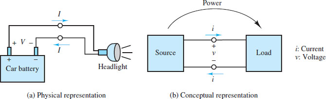
Figure 1a Physical and conceptual representations of an electrical system. Recall the notation rules for V, I, v.
The use of the term source can be confusing at times because there are circuit elements known as ideal voltage and current sources, which have well-defined attributes and circuit symbols.
These ideal sources, along with other circuit elements, are often the constituents of the source portion of a circuit, as well as the load portion. Other key conceptual features of electric circuits are the ideal wire, node, branch, loop, and mesh. The concept of a node is particularly useful for correctly interpreting circuit diagrams.
Many students struggle with circuit analysis simply because they lack an organizing perspective with which to interpret circuit diagrams. One particularly helpful perspective is to see electric circuits as comprised of elements situated between nodes. Once the concept of a node is well understood this perspective simplifies and clarifies many circuits that otherwise appear complicated.
Ideal Wire
Electric circuit and network diagrams are used to represent (approximately) actual electric circuits and networks. These diagrams contain elements connected by ideal wires. An ideal wire is able to conduct an electric charge without any loss of electric potential. In other words, no work is required to move an electric charge along an ideal wire.
Luckily, in many applications, actual wires are well approximated by ideal wires. However, there are applications where wiring accounts for significant losses of potential (e.g., long-distance transmission lines and microscopic integrated circuits). In these applications, the ideal wire approximation must be augmented and/or used with care.
Node
A node consists of one or more ideal wires connected together such that an electric charge can travel between any two points on the node without traversing a circuit element, such as a resistor.
It is important to recognize that since a node consists of ideal wires only, every point on a node has the same electric potential, which is known as the node voltage and its value is relative to the other nodes in the network.
The junction of two or more ideal wires is often used to represent an entire node; however, it is important to recognize that a wire junction is not the entire node and that a node may contain multiple wire junctions. It is crucial to correctly identify and count nodes in the analysis of electric circuits.
Figure 2 illustrates a helpful way to mark nodes. There are three nodes in Figure 2a and two nodes in Figure 2b. It is sometimes convenient to use the concept of a super node, which is simply a closed boundary enclosing two or more nodes, as shown in Figure 2c.
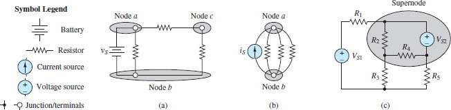
Figure 2 Illustrating nodes and super nodes in circuit diagrams
It is also important to realize that since no work is required to move an electric charge along an ideal wire, the length and shape of an ideal wire has no impact on the behavior of a circuit.
Likewise, since nodes are comprised of ideal wires, the extent, and shape of a node has no impact on the behavior of a circuit. As a result, a node may be redrawn in any manner as long as the newly drawn node is attached to the same elements as the original node.
Circuit diagrams are typically drawn, by convention, in a rectangular manner, with all wires drawn either side to side or up and down. However, many students find it helpful to redraw circuits so as to clarify the number and location of nodes in a circuit.
Figure 3 shows two identical circuits drawn in two different ways. Can you tell that these circuits have the same number of nodes?
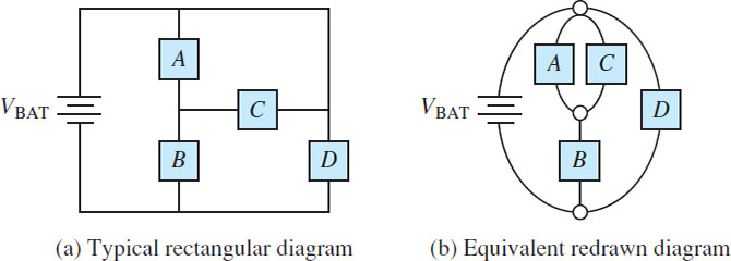
Figure 3a A typical rectangular circuit diagram and 3b an equivalent redrawn diagram. A circuit can be redrawn to have almost any appearance; however, the nature of the circuit is unchanged if the number of nodes and the elements between those nodes remains unchanged.
Keep in mind that all forms of potential, including voltage, are relative quantities. For this reason, it is common to refer to the change in voltage across an element, or simply the voltage across an element.
In circuit diagrams, a change in voltage across an element is indicated by the paired symbols + and −. Taken together as a single symbol they indicate the assumed direction of the change in voltage. However, as mentioned above, it is also common to refer to a node voltage.
To quantify a node voltage, it is first necessary to select a reference node. Then, one can refer to the voltage of a node with the understanding that the value of that voltage is relative to the chosen reference node.
Reference Node
Any one node in a network can serve as the reference. The reference node and its value can be chosen freely, although a value of zero is usually chosen, for simplicity.
It is often true that a smart choice of reference node will simplify the analysis that follows. A good rule of thumb is to select a node that is connected to a large number of elements.
A reference node is designated by the symbol shown in Figure 4a. This symbol is also used to designate earth ground in applications. It is common for this symbol to appear multiple times in complicated circuits. Still, there is only one reference node per circuit. To reduce the apparent complexity of such circuits, multiple reference symbols are used to minimize the amount of displayed reference node wiring. It is simply understood that all nodes to which these symbols are attached are, in fact, connected by ideal wires and therefore part of one large reference node. Figure 4b and 4c illustrate this practice.
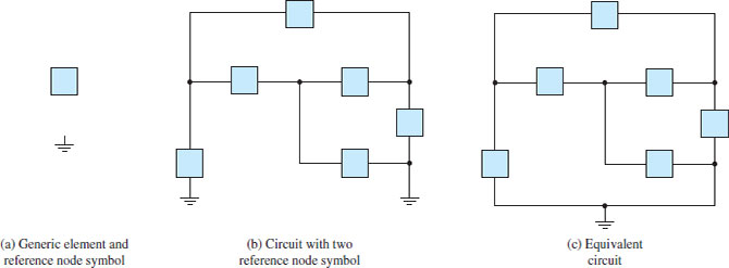
Figure 4 There can be one and only one reference node in a network although the reference node symbol may appear more than once in order to reduce the amount of displayed reference node wiring.
Elements that sit between the same two nodes are said to be in parallel.
Branch
A branch is a single electrical pathway, consisting of wires and elements. A branch may contain one or more circuit elements as shown in Figure 5. By definition, the current through any one element in a branch is the same as the current through any other element in that branch; that is, there is one current in a branch, the branch current.
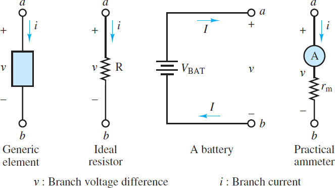
Figure 5 Examples of circuit branches
Elements that sit along the same branch are said to be in series.
Loop
A loop is any closed pathway, physical or conceptual, as illustrated in Figure 6.
Figure 6a shows that two different loops in the same circuit may share common elements and branches. It is interesting, and perhaps initially confusing, to note that a loop does not necessarily have to correspond to a closed electrical pathway, consisting of wires and elements. Figure 6b shows one example in which a loop passes directly from node a to node c.
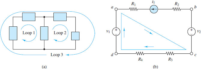
Figure 6 Examples of loops. How many nodes are in each of these circuits? [Answers: (a) 4; (b) 7]
Mesh
A mesh is a closed electrical pathway that does not contain other closed physical pathways. In Figure 6a, loops 1 and 2 are meshes, but loop 3 is not a mesh because it encircles the other two loops. The circuit in Figure 6b has one mesh. Figure 7 illustrates how simple it is to visualize meshes.

Figure 7 Circuit with four meshes. How many different closed electrical pathways are in this circuit? [Answer: 14]
Example 1 Counting nodes in a network
Find the total number of nodes in each of the four networks.
Solution
Known Quantities: Wires and elements.
Find: The number of nodes in each network diagram.
Schematics, Diagrams, Circuits, and Given Data: Figure 8 contains four elements: two resistors and two ideal voltage sources, one independent and one dependent. Figure 9 contains five elements: four resistors and one independent ideal current source. Figure 10 contains five elements: four resistors and one operational amplifier. Figure 11 contains three elements: two headlamps and one 12-V battery.
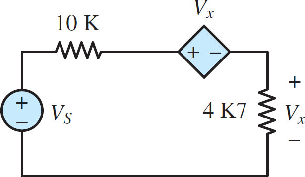
Figure 8: Electric Circuit with Four Elements
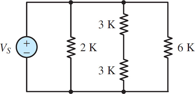
Figure 9 Electric Circuit with Five Elements
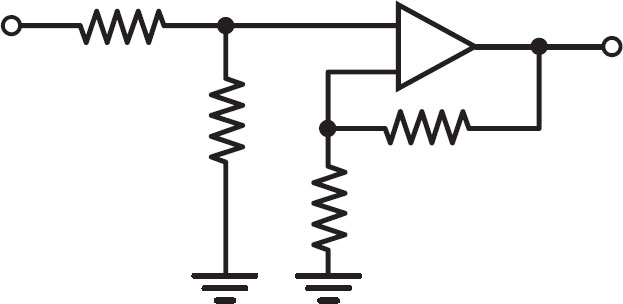
Figure 10 Circuit Containg Five Elements
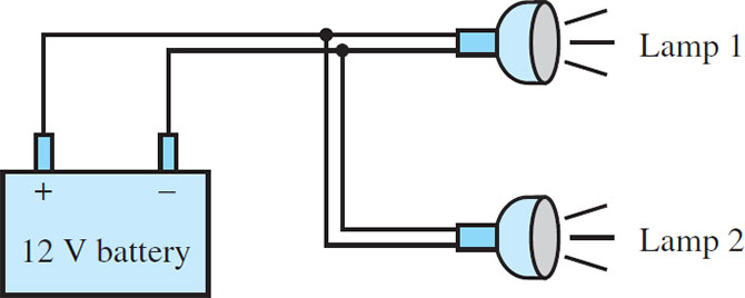
Figure 11 Circuit Containing Three Elements
Assumptions: All wires are ideal.
Analysis:
In Figure 8, all four elements are in a single electrical loop. There is one node between each pair of elements. Thus, there are four nodes in this network.
In Figure 9, the current source and the two 8-kΩ resistors sit between two large nodes, one along the top of the network and the other along the bottom of the network. Each of these nodes contains two wire junctions. Another node is between the two 6-kΩ resistors. Thus, there are three nodes in this network.
In Figure 10, there is one node to the left of R1 and one node to the right of the operational amplifier and RF. A third node is located between R1, R2, and the + (non-inverting) terminal of the operational amplifier. A fourth node is located between R3, RF, and the − (inverting) terminal of the operational amplifier. A fifth, and final, node is the reference node, which is between R2 and R3. Thus, there are five nodes in this network.
In Figure 11, there is one node between the positive + battery terminal and the two headlamps and one node between the positive + battery terminal and the two headlamps and one node between the negative − battery terminal and the two headlamps. Thus, there are two nodes in this network.
Comments: Notice that no knowledge of the elements is required to identify and count the nodes in a network.
Characteristics of Network and Electric Circuit Key Takeaways
Understanding the concepts of network and electric circuit is fundamental to the analysis, design, and operation of all modern electrical and electronic systems. These principles are not only essential for academic learning but also play a critical role in real-world applications such as power distribution, communication systems, consumer electronics, automotive systems, and industrial automation. By grasping the relationships between elements like current, voltage, nodes, branches, loops, and meshes, engineers can design more efficient and reliable circuits. Moreover, circuit diagrams and analysis methods provide a clear framework to troubleshoot, optimize, and innovate within countless technologies we rely on every day. Hence, a strong foundation in network and circuit theory is indispensable for anyone working in or studying electrical and electronic engineering.