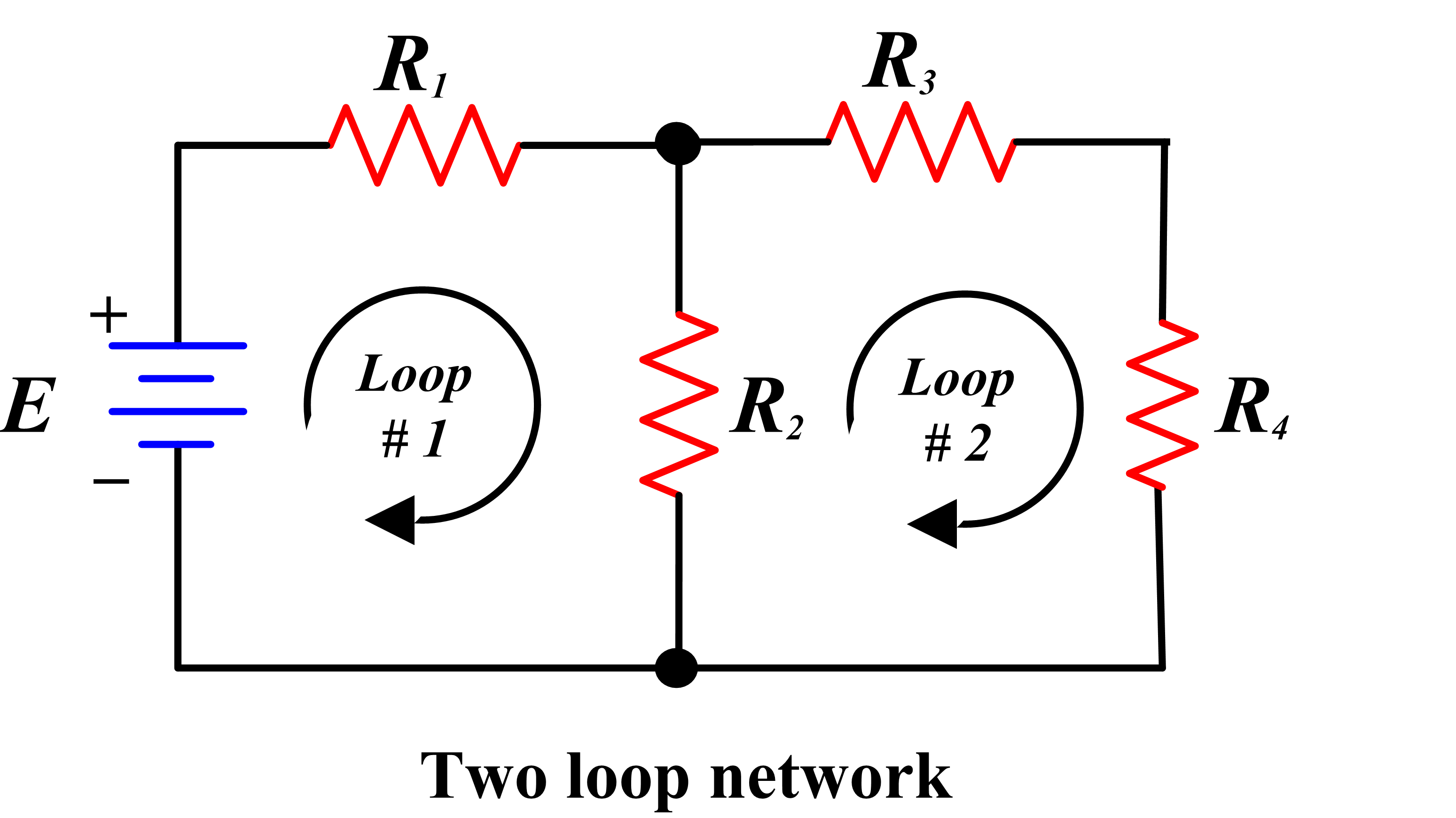
Another method of circuit analysis employs mesh currents. The objective, similar to that of node analysis, is to generate one independent equation for each independent variable in a circuit.
In this method, each mesh in a circuit is assigned a mesh current variable and Kirchhoff’s voltage law (KVL) is applied at some or all of the meshes to generate a system of equations that relate these variables.
It is important to recall that mesh currents are not the same as branch currents. The perspective taken in the mesh current method is that there is one current circulating within each mesh and that branch currents in the circuit are comprised of these mesh currents.
Specifically, when a branch is part of only one mesh, the branch current is the same as that mesh current. However, when a branch is shared by two meshes, the branch current is comprised of two mesh currents.
In the mesh current method, it is necessary to assume a direction for the circulation of each mesh current. A helpful convention is to assume that all mesh currents circulate in the clockwise (CW) direction. With this convention, when a branch is shared by two meshes, the branch current is equal to the difference of two mesh currents. This result is illustrated in Figure 1 where the current through resistor R2 is the difference of i1 and i2. The voltage drop across R2 is given by Ohm’s law as either:
$\left( {{i}_{1}}-{{i}_{2}} \right){{R}_{2}}$
Or
$\left( {{i}_{2}}-{{i}_{1}} \right){{R}_{2}}$
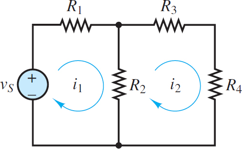
Figure 1 Two meshes
Which of these expressions is the right one to use? The answer depends upon the convention used when applying KVL.
To avoid confusion when expressing Ohm’s law, it is helpful to always apply KVL around a mesh in the same direction (e.g., CW) used to define the mesh current. This approach is helpful because Ohm’s law implies that current through a resistor is directed from high to low voltage, as shown in Figure 2, and that the change in voltage is proportional to the net current through the resistor. Thus, when KVL is applied in the same direction as the mesh current (e.g., i1), the voltage drop across a resistor in that mesh will be represented in the same direction as the mesh current (see Figure 3) and equal to either:
$\begin{matrix}{{v}_{1}}={{i}_{1}}{{R}_{1}} & {} & \left( 1 \right) \\\end{matrix}$
Or
$\begin{matrix}{{v}_{2}}=\left( {{i}_{1}}-{{i}_{2}} \right){{R}_{2}} & {} & \left( 2 \right) \\\end{matrix}$
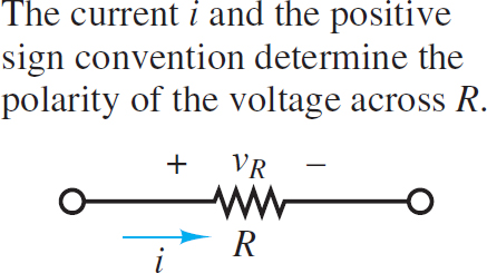
Figure 2 Ohms law implies that current is directed from high (+) to low (-) potential.
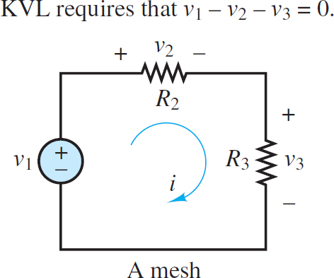
Figure 3 Use of KVL in mesh analysis
Notice that the net current through R2 in the direction of mesh current i1 is (i1 – i2). The following procedure outlines the steps taken in applying the mesh current method to a linear circuit.
Mesh Analysis Step by Step Guide
1. Select a circulation convention (either CW or CCW) for the mesh currents and KVL.
2. Define mesh current variables i1 i2,…, in for each of the n meshes.
• If the circuit contains no current sources, then all n mesh currents are treated as independent variables.
• If the circuit contains m current sources:
◦ There are n − m independent variables.
◦ There are m dependent variables.
◦ When a current source borders only one mesh, the value of that mesh current is dictated by the current source. Treat that mesh current as a dependent variable.
◦ When a current source borders two meshes, the value of the difference in those mesh currents is dictated by the source. Treat one of those mesh currents as a dependent variable and the other as an independent variable.
3. Apply KVL at each mesh associated with an independent variable, using Ohm’s law to express each resistor voltage drop in terms of the adjacent mesh currents.
• For each current source is there will be one additional dependent equation (e.g. is =ik −ij).
4. Collect coefficients for each of the n variables and solve the linear system of n equations.
• Some of the dependent equations may have the simple form ij =is. In this case, the total number of equations and variables is reduced by direct substitution.
5. Use the known mesh currents to solve for any or all branch currents in the circuit. Any voltage drop can be found by applying Ohm’s law and, when necessary, KVL.
This procedure can be used to find a solution for any planar circuit. A good approach is to first practice solving circuits without any current sources and then learn to deal with the added complexity of circuits with current sources.
Details and Examples
In Figure 4, there are two meshes, each with a defined clockwise mesh current. There are no current sources in the circuit, so there are two independent mesh current variables i1 and i2. The KVL equation for mesh i1 is:
$\begin{matrix}{{v}_{s}}-{{i}_{1}}{{R}_{1}}-\left( {{i}_{1}}-{{i}_{2}} \right){{R}_{2}}=0 & mesh\text{ }1 & \left( 3 \right) \\\end{matrix}$
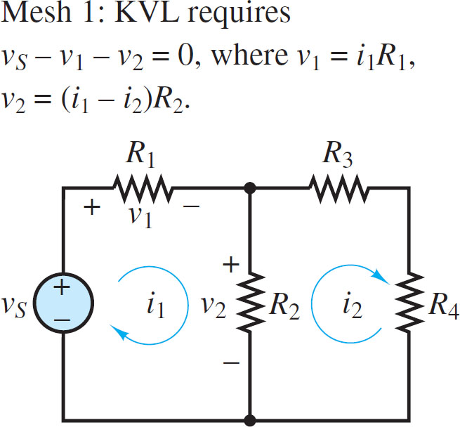
Figure 4 Assignment of currents and voltages around mesh 1
When KVL is applied to mesh i2, the net current through R2 in the direction of mesh current i2 is (i2 – i1). Thus, the KVL equation for mesh i2 (see Figure 5) is:
$\begin{matrix}-\left( {{i}_{2}}-{{i}_{1}} \right){{R}_{2}}-{{i}_{2}}{{R}_{3}}-{{i}_{2}}{{R}_{4}}=0 & mesh\text{ }2 & \left( 4 \right) \\\end{matrix}$
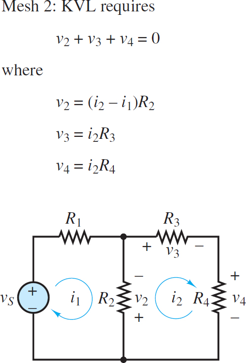
Figure 5 Assignment of currents and voltages around mesh 2
Multiply both sides of the mesh 2 equation by −1. Then, collect coefficients of i1 and i2 in each equation to yield the following system of equations:
$\begin{matrix} \left( {{R}_{1}}+{{R}_{2}} \right){{i}_{1}}-{{R}_{2}}{{i}_{2}}={{v}_{s}} & {} & {} \\ {} & {} & \left( 5 \right) \\ -{{R}_{2}}{{i}_{1}}+\left( {{R}_{2}}+{{R}_{3}}+{{R}_{4}} \right){{i}_{2}}=0 & {} & {} \\\end{matrix}$
These two equations can be solved simultaneously for the two independent mesh current variables i1 and i2. The branch current through R2 can then be found as well. If the resulting numerical answer for a mesh current is negative, then the actual direction for that mesh current is opposite of the defined direction.
Note that the expressions for the voltage drop across R2 in the two KVL equations are different because the same clockwise convention is used in both meshes for KVL.
In mesh 1, the KVL loop traverses R2 from top to bottom while in mesh 2 the KVL loop traverses R2 from bottom to top. The result is a potential source of confusion and error when applying the mesh current method.
A careful determination of the voltage drops around each mesh, one mesh at a time, and in accord with the positive sign convention for Ohm’s law, is necessary for success.
Mesh Analysis with Current Sources
It is common, in practice, to encounter current sources in electric circuits. The relevant steps found in the above section are listed below with added comments.
Step 1: Select a circulation convention (either CW or CCW) for the mesh currents and KVL.
Step 2: Define mesh current variables i1, i2, . . . in for each of the n meshes. If the circuit contains m current sources:
• There are n − m independent variables.
• There are m dependent variables.
• When a current source borders only one mesh, the value of that mesh current is dictated by the current source. Treat that mesh current as a dependent variable.
• When a current source borders two meshes, the value of the difference in those mesh currents is dictated by the source. Treat one of those mesh currents as a dependent variable and the other as an independent variable.
The circuit in Figure 6 has two meshes and one current source. Thus, there is one independent mesh current variable i1 and one dependent mesh current variable i2. Note that the circulation of i1 indicates a clockwise convention. With that convention, i2 has the opposite direction of is in the rightmost branch. Thus, i2 = −is and Figure 6 shows the second mesh current as is circulating counterclockwise.
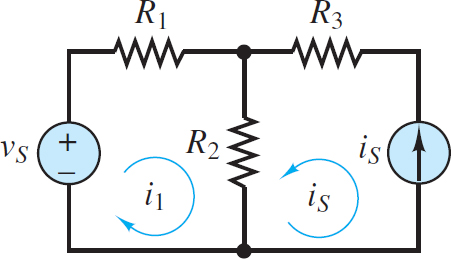
Figure 6 Mesh analysis with current sources
Step 3: Apply KVL at each mesh associated with an independent variable, using Ohm’s law to express each resistor voltage drop in terms of the adjacent mesh currents.
• For each current source iS there will be one additional dependent equation (e.g., is = ik – ij).
The one dependent equation is, of course:
${{i}_{2}}=-{{i}_{s}}$
KVL around the i1 mesh yields:
$\begin{matrix} {{v}_{s}}-{{R}_{1}}{{i}_{1}}-{{R}_{2}}\left( {{i}_{1}}+{{i}_{s}} \right)=0 & {} & {} \\ {} & {} & \left( 6 \right) \\ \left( {{R}_{1}}+{{R}_{2}} \right){{i}_{1}}={{v}_{s}}-{{R}_{2}}{{i}_{s}} & {} & {} \\\end{matrix}$
Step 4: Collect coefficients for each of the n variables and solve the linear system of n equations.
• Some of the dependent equations may have the simple form ij = is. In this case, the total number of equations and variables is reduced by direct substitution.
The presence of the current source has simplified the problem. There is only one unknown mesh current, i1, and one equation.
\[\begin{matrix} {{i}_{1}}=\frac{{{v}_{s}}-{{R}_{2}}{{i}_{s}}}{{{R}_{1}}+{{R}_{2}}} & {} & \left( 7 \right) \\\end{matrix}\]
Step 5: Use the known mesh currents to solve for any branch current in the circuit. Any voltage drop can be found by applying Ohm’s law and, when necessary, KVL.
By inspection, the current through R1 is i1 and the current through R3 is iS. The current through R2 is i1 + iS. The change in voltage across the current source, with respect to the reference node, is given by KVL as:
$\begin{matrix}{{i}_{s}}{{R}_{3}}+\left( {{i}_{1}}+{{i}_{s}} \right){{R}_{2}} & {} & \left( 8 \right) \\\end{matrix}$
It is important to understand that Mesh or Loop analysis can be applied to either AC resistive circuit or DC resistive circuit. In any type of network, the numbers of linear equations are dependent on the number of loop currents.
