The article provides an overview of operational amplifier (op-amp), discussing their basic structure, internal operation, and various types of control systems (open-loop and closed-loop) in which they are used. It also highlights the advantages of op-amps and explores a range of practical applications, including amplification, signal conversion, and control systems.
An operational amplifier (op-amp) is a high-gain, directly coupled amplifier that uses external feedback to control response characteristics. See Figure 1.
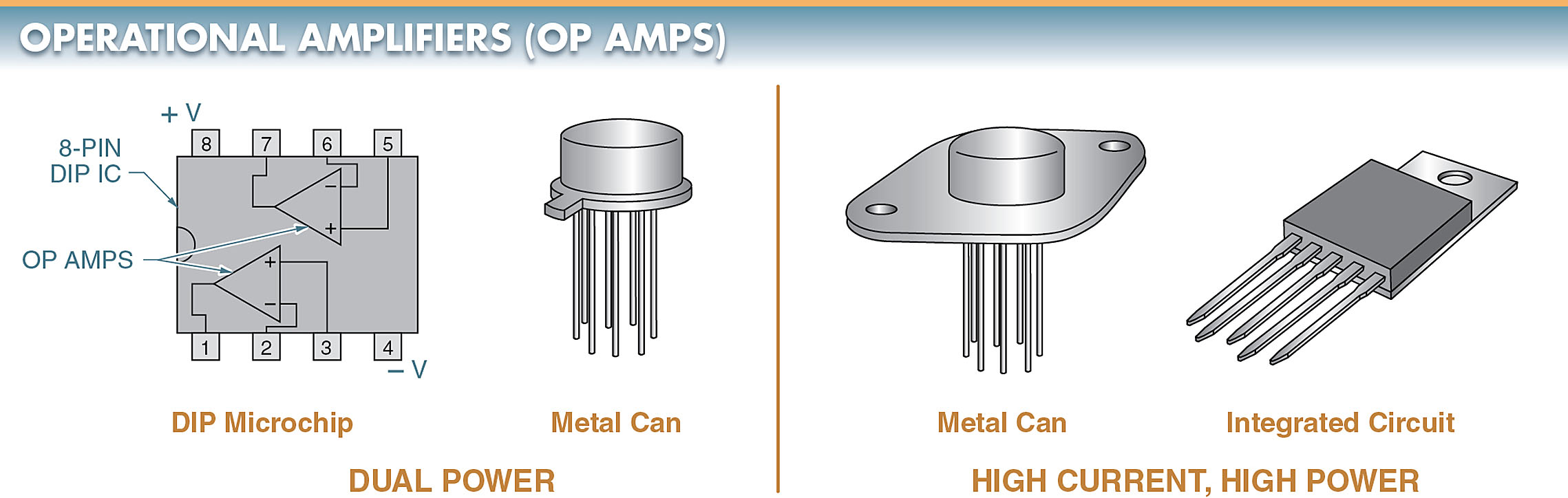
Figure 1. Types of operational amplifiers (op-amps) include dual-power and high-current, high-power op-amps.
An example of feedback control is gain. The gain of an op-amp can be controlled externally by connecting a feedback resistor between the output and input.
A number of different amplifier applications can be achieved by selecting different feedback components and combinations. With the right component combinations, gains in the thousands are common.
An op-amp is very versatile. An op-amp can be made to perform math functions, such as addition, subtraction, multiplication, and division, by connecting it to a few components.
Today, the main purpose of an op-amp is to amplify small signals to levels that can be used for the control of another device. An op-amp is often used in digital circuits that require the analog amplification of a weak signal.
Operational Amplifier Schematic Symbols
The schematic symbol of an operational amplifier may be shown as a triangle with the two inputs of the op-amps as inverting (–) and noninverting (+). See Figure 2.
The two inputs are usually drawn with the inverting input at the top. The exception to the inverting input being at the top is when it would complicate the schematic symbol.
In either case, the two inputs should be clearly identified on the schematic symbol by polarity symbols.
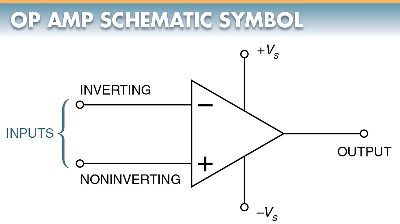
Figure 2. The schematic symbol for an op-amp includes inverting (–) and noninverting (+) inputs.
Operational Amplifier Advantages
The advantages of an operational amplifier include the following:
- high input impedance (resistance) —an operational amplifier does not draw much power from the input source
- low output impedance—a high output impedance would reduce the amplified output
- high gain—one operational amplifier can replace many individual transistors
Op-Amp Voltage Source
Like other solid-state devices, ICs need DC operating voltages. The DC voltage pins on some ICs are labeled common-collector voltage (VCC). Other pins are labeled as input voltage (Vin) or supply voltage (VS). DC voltage ratings in IC databooks are labeled all three ways.
The voltage source for op-amps can be a single supply. However, they are usually bi-polar or dual supply. See Figure 3.
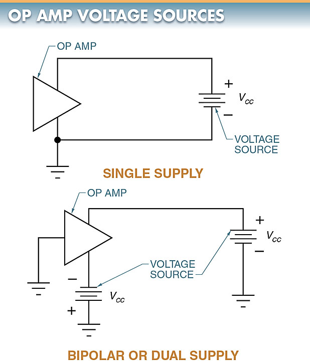
Figure 3. While voltage sources for op-amps can be single supply, they are usually bi-polar or dual supply.
Internal Op-Amp Operation
Internally, an op-amp has three major sections. It consists of a high-impedance differential amplifier, a high-gain stage, and a low-output impedance power-output stage.
The differential amplifier provides wide bandwidth and high impedance. The high-gain stage boosts the signal. The power-output stage isolates the gain stage from the load and provides power. See Figure 4.
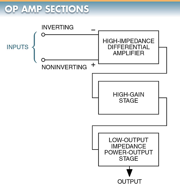
Figure 4. Internally, an op-amp consists of a high-impedance differential amplifier, a high-gain stage, and a low-output impedance power-output stage.
Operational Amplifier Gain
Op-amps may have gains of 500,000 or more, no gain (unity gain), or controlled gain. The gain in an op-amp is controlled by external resistors that provide closed-loop feedback.
In the high-gain mode, a very small change in voltage on either input results in a large change in the output voltage. These high-gain circuits can be far too sensitive and unstable for most applications.
The gain is normally reduced to a much lower level due to this instability. The circuit is stabilized by feeding back some of the output signals to one of the inputs through a resistor.
Voltage Followers (Unity-Gain)
A voltage follower, or source follower, is a noninverting amplifier. The output voltage (Vout) is an exact reproduction of the input voltage (Vin). See Figure 5.
The function of the voltage follower is identical to that of the source follower created by a bipolar transistor and FET. The circuit is used to impedance-match an input signal to its load.
With the voltage follower, the input impedance is high and the output impedance is low. It should be noted that the voltage follower has no input or feedback components. Because no feedback components are used in this type of circuit, the amplifier is operating in a unity-gain condition.
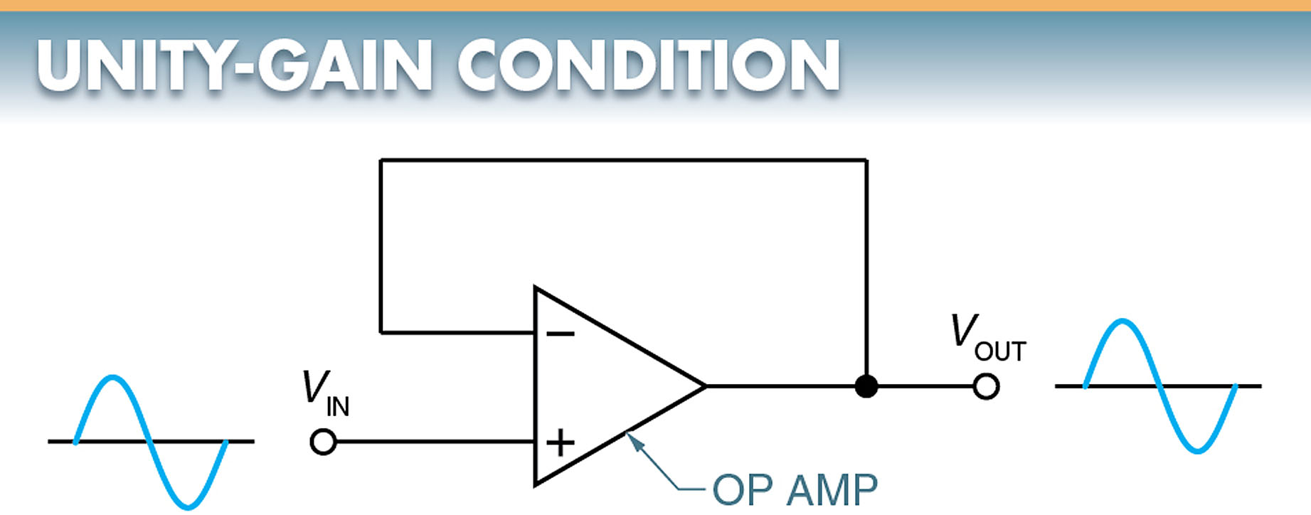
Figure 5. An amplifier is operating in a unity-gain condition when the output voltage is an exact reproduction of the input voltage.
Open-Loop Control
Open-loop systems are used almost exclusively for manual control operations. The two variations of the open-loop system are full control and partial control.
Full control operation simply turns a system on or off. For example, in an electrical circuit, current flow stops when the circuit path is opened. Switches, circuit breakers, fuses, and relays are used for full control.
Partial control operation alters system operations rather than causing them to start or stop. Resistors, inductors, transformers, capacitors, semiconductor devices, and ICs are commonly used to achieve partial control.
Closed-Loop Control
To achieve automatic control, the interaction between the control unit and the controlled element must occur. In a closed-loop system, this interaction is called feedback. Feedback can be activated by electrical, thermal, light, chemical, or mechanical energy.
Both full and partial control can be achieved through a closed-loop system. See Figure 6.
Many of the automated systems used in industry today are of the closed-loop type. A closed-loop system may have automatic correction control.
Closed-Loop System Working
In the system, the energy goes to the control unit and the controlled element. Feedback from the controlled element is directed to a comparator, which compares the feedback signal to a reference signal or standard. A correction signal is developed by the comparator and sent to the control unit. This signal alters the system so that it conforms to the data from the reference source.
Systems of this type maintain a specified operating level regardless of external variations or disturbances.
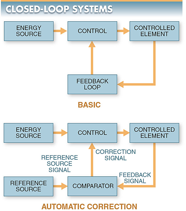
Figure 6. Closed-loop systems may be depicted by block diagrams.
Automated control has gone through many changes in recent years with the addition of control devices that are not obvious to the casual observer. These include devices that change the amplitude, frequency, waveform, time, or phase of signals passing through the system.
Feedback Inverting Amplifiers (Closed-Loop)
A feedback inverting amplifier produces a 180° phase inversion from input (Vin) to output (Vout). See Figure 7. When a positive-going voltage is applied to the input, a negative-going voltage will be produced at the output.
The input signal is applied to the op-amp inverting input through R1, while resistor R2 serves as the feedback element.
The voltage gain of the feedback inverting amplifier can be less than, equal to, or greater than 1.0. Its value depends on the values of resistors R1 and R2. Because a feedback component is used in this type of circuit, the amplifier is operating in a closed-loop condition.
The closed-loop gain of the feedback inverting amplifier can be controlled by switching in different feedback resistors.
Offset Error and Nulling
Although extreme care is taken in fabricating an op-amp, a slight mismatch may still occur between the internal components.
Offset error is a slight mismatch between internal components. Offset error creates a problem when using an op-amp in a DC circuit. The mismatch prevents the amplifier from having a zero output for zero input.

Figure 7. Feedback inverting amplifier produces a 180° phase inversion from input to output.
Even with proper bias, the feedback inverting amplifier has an input bias current (IB) through the input and feedback resistors with no signal applied. The additional current flow through these resistors produces a voltage drop, which appears as the DC input voltage. The op-amp then amplifies this DC input voltage, compounding the offset error.
To correct the offset error, the nulling technique is often used through a nulling resistance network. With this network, the nulling variable resistor is adjusted for zero output with zero input.
Operational amplifier (Op-Amp) Applications
Op-amps are used for a variety of amplification applications. For example, they are used in audio amplifiers and video amplifiers. They are also ideal for a variety of industrial and commercial control systems.
Current-to-Voltage Converters
A current-to-voltage op-amp uses the current sensitivity of the op-amp to measure very small currents. The circuit can provide 1 V at the output for 1 μA at the input.
This basic current-to-voltage converter is essentially an inverting amplifier without an input resistor. The input current is applied directly to the inverting input of the op-amp.
A thermistor varies the amount of current (Iin) entering the inverting input of the op-amp. See Figure 8.
As the ambient temperature around a thermistor increases, the resistance of the thermistor decreases, current to the input of the op-amp increases, and the voltage at the output increases.
As the temperature decreases, the resistance increases, current decreases, and voltage output decreases. Since the output of the circuit is now voltage, the op-amp voltage can be used to drive an output device.
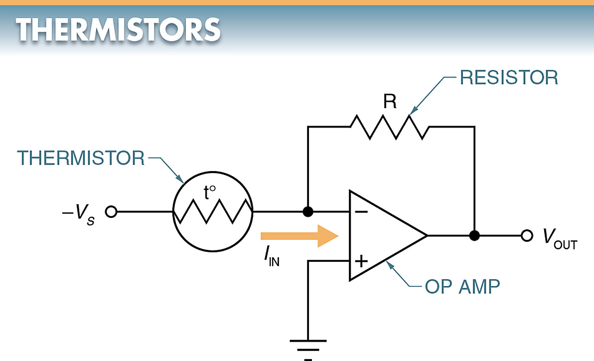
Figure 8. As the ambient temperature around a thermistor changes, the resistance of the thermistor changes.
Voltage-to-Current Converters
In certain circuits, such as a circuit in an air compressor, a change in voltage becomes the reference for the change in the circuit. When this is the case, a voltage-to-current op-amp is used. See Figure 9.
The output voltage of the bridge circuit is a function of the degree of imbalance present in the input bridge. For the bridge circuit, an imbalance can be created by changing the pressure on the pressure sensor (transducer). The potentiometer determines the pressure-set limits.
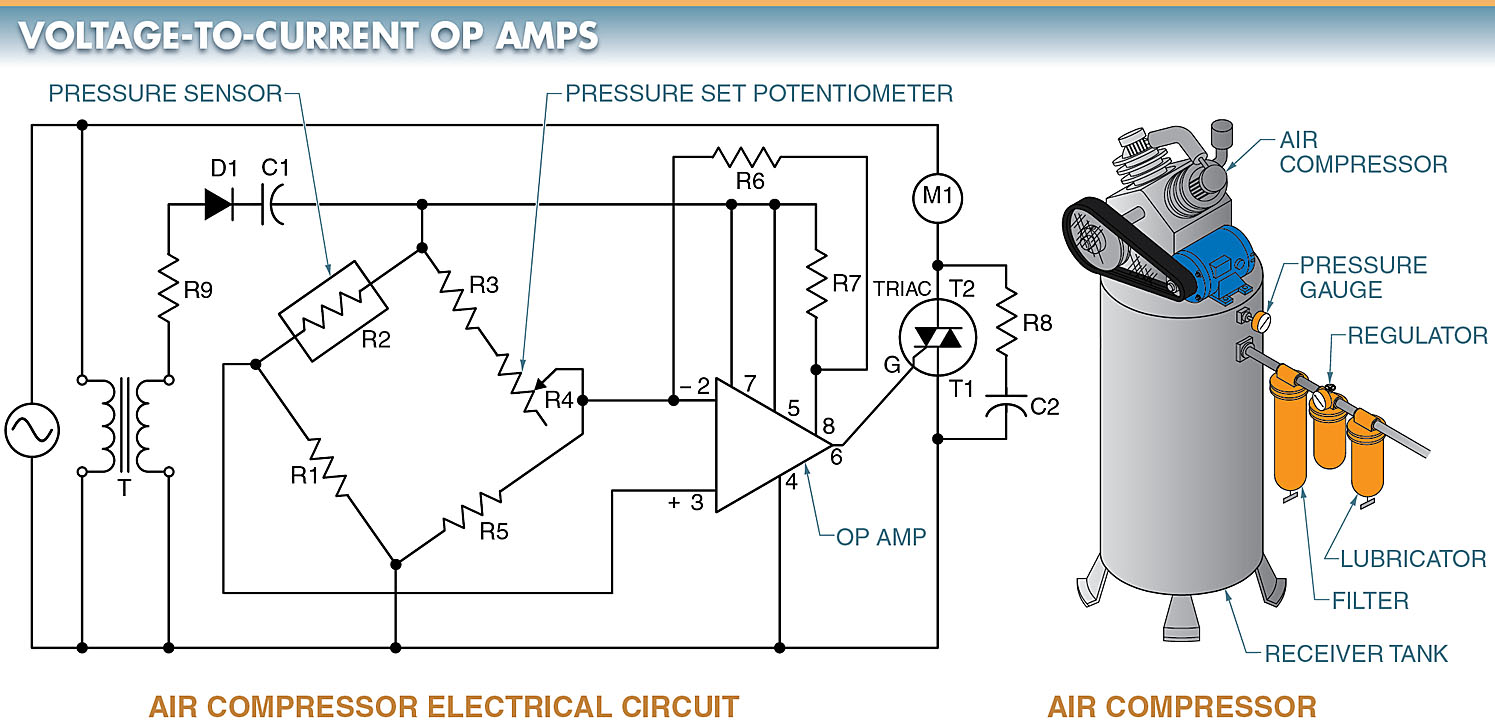
Figure 9. A voltage-to-current op-amp can be used to control an air compressor.
The unit can operate directly from the AC supply since it includes a step-down transformer and a single-phase rectifier.
When the pressure drops, the resistance of the pressure sensor decreases. Terminal 3 of the op-amp becomes more positive than terminal 2. Under this condition, the output current at pin 6 causes the triac to conduct.
With the triac conducting, power is applied to the coil, which turns on the air compressor. When the pressure in the tank is brought up to the preset limit, the value of the pressure sensor increases, balancing the bridge, and the air compressor shuts off.
Thermostat Control
An op-amp can be used as a differential amplifier. A differential op-amp is a type of op-amp used in differential thermostat controls for solar water heaters. See Figure 10.
Small signal changes can be detected easily in the circuit and are amplified for signaling or control purposes. Because the output of an op-amp has very little power, an interface device, such as a control relay, must be used to control higher power loads, such as a water pump in a hot water system.
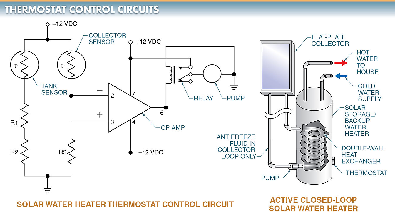
Figure 10. A differential op-amp can be used in a solar water heater thermostat control circuit.
When the op-amp has signals of equal amplitude and polarity applied to each of its inputs simultaneously, the output will be zero.
For the circuit, the bridge must be balanced for the op-amp output to be zero. The bridge is formed by a tank sensor; collector sensor; and resistors R1, R2, and R3.
If the tank senses a reduction in temperature, the bridge will become unbalanced, with the difference being presented to the input of the op-amp. The signal is amplified to the output. The output is then connected to a relay that starts the pump.
When enough hot water passes the collector and tank and heats the tank water, the bridge is again balanced and the relay is turned off.
Operational Amplifier (Op Amp) Key Takeaways
Understanding the structure, internal operation, and control systems of operational amplifier is crucial because these characteristics directly influence their effectiveness in real-world applications. Op-amps are foundational components in modern electronics, offering high versatility, stability, and precision. Their role in amplification, signal conversion, and control systems enables the development of sensitive measurement tools, responsive automation systems, and efficient power control solutions. From industrial automation to consumer electronics and renewable energy management, the practical applications of op-amps—such as voltage and current converters or thermostat control—demonstrate their vital importance in improving performance, reliability, and adaptability in a wide range of systems.