The article discusses various practical applications of electromagnets, including crane electromagnets, solenoids, solenoid valves, transformers, control relays, electric generators, and electric motors. It covers the principles behind each application, such as the control of magnetic strength, the operation of solenoids, and the function of transformers and motors in converting electrical energy to mechanical energy and vice versa.
Electromagnets can be made much more powerful than permanent magnets. In addition, the strength of the electromagnet can be easily controlled from zero to maximum by controlling the current flowing through the coil. For these reasons, electromagnets have many more practical applications than do permanent magnets.
Crane Electromagnets
One of the most graphic examples of a working electromagnet is the one for cranes that are used to move scrap iron. The crane electromagnet shown in Figure 1 is a big block of soft iron that is magnetized by an electric current flowing through a coil.
This type of electromagnet has the capability of lifting heavy loads of magnetic scrap metal. Lift-and-drop control is easily accomplished by the connection and disconnection of voltage to the electromagnet.
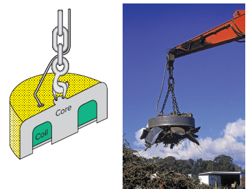
Figure 1 Crane electromagnets.
Solenoids
A solenoid is an electromagnet with a movable iron core or plunger. Upon applying power or energizing the coil, the magnetic field that is produced pulls or pushes the plunger into the coil, as illustrated in Figure 2.
Whenever power is applied to the coil, the plunger is magnetically attracted into the stator as it slides along a nylon surface in a linear fashion. By attaching a nonferrous push rod to the plunger, a pushing or pulling motion can be accomplished.
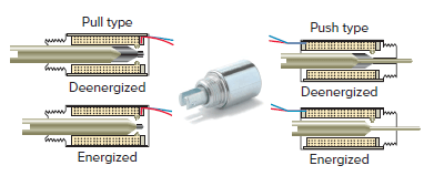
Figure 2 Solenoid.
Solenoid Valves
Solenoid valves are the most frequently used device to control liquid or gas flow. A solenoid valve has two main parts: the solenoid and the valve. Figure 3 shows a typical solenoid valve. One inlet and one outlet are used to permit and shut off fluid flow. A spring is used to hold the valve closed when the solenoid coil is de-energized. When the coil is energized, the magnetic field created pulls the plunger upward to open the valve, permitting liquid flow from inlet to outlet.
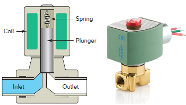
Figure 3 Solenoid valve.
Transformers
Most home heating/cooling system’s thermostats operate on low-voltage (typically 24 volts AC) control circuits. The source of the 24-volt AC power is a control transformer installed as part of the heating/cooling equipment.
The advantage of the low-voltage control system is the ability to operate system load devices using inherently safe voltage and current levels.
Transformers are electrical devices that are used to raise or lower AC voltages. Figure 4 is a typical step-down control transformer. The transformer uses two electromagnetic coils to transform or change the AC input voltage level.
An input voltage of 120 VAC is applied to the primary coil wound around an iron core. An output voltage of 24 VAC emerges from a secondary coil also wound around the core.
The AC voltage input current produces a magnetic field that continually varies in magnitude. The core transfers this field to the secondary coil where it induces an output voltage. The change in voltage depends on the ratio of turns in the primary and secondary coils.

Figure 4 Step-down control transformer.
Electricity is generated at a comparatively low voltage. In order to transport this energy great distances, the voltage has to be increased, or stepped up, to values as high as 765,000 volts. This is accomplished through the use of large step-up transformers located near the generating station and provides an efficient and economical method of transmission. A series of transformers then step-down the voltage to levels that are safe in businesses and residences.
Control Relays
An electromagnetic control relay is a switch that is operated by an electromagnet. The relay generates electromagnetic force when input voltage is applied to the coil. The electromagnetic force moves the armature that switches the contacts.
A relay is made up of two circuits: the coil input or control circuit and the contact output or load circuit, as illustrated in Figure 5. Relays are used to control small loads of 15 A or less, which include solenoids, pilot lights, alarms, and small fan motors.
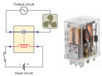
Figure 5 Electromagnetic control relay.
Electric Generators
An electric generator is a machine that uses magnetism to convert mechanical energy into electric energy. Generators can be subdivided into two major categories depending on whether the electric current produced is alternating current (AC) or direct current (DC).
The basic principle on which both types of generator work is the same, although the details of construction of the two may differ somewhat.
The generator principle states that a voltage is induced in a conductor whenever the conductor is moved through a magnetic field so as to cut lines of force. Figure 6 illustrates the generator principle and relationships between the direction the conductor is moving, the direction of the magnetic field, and the resultant direction of the induced current flow.
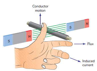
Figure 6 Generator principle.
In its basic form the AC generator consists of a magnetic field, an armature, slip rings, and brushes. For most applications the magnetic field is created by an electromagnet, but for the simple generator shown in Figure 7, permanent magnets are used.
The armature is rotated through the magnetic field and may contain any number of conductors wound in loops. As the armature is rotated, a voltage is generated in the single loop conductor which causes current to flow. Slip rings are attached to the armature and rotate with it. Carbon brushes ride against the slip rings and conduct the current from the armature to the output load.
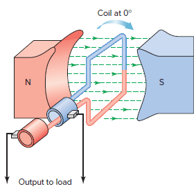
Figure 7 Basic AC generator.
As the armature is rotated through one complete revolution, an AC sine wave voltage is produced, as illustrated in Figure 8. This generated voltage varies in both voltage value and polarity as follows:
- At 0 degrees the coil is moving parallel to the magnetic field. It cuts no lines of force, so no voltage is generated.
- When the coil rotates from 0 to 90 degrees, it cuts more and more lines of flux. As the lines of flux are cut, voltage is generated in the positive direction and reaches a maximum value at 90 degrees.
- As the coil continues to rotate from 90 to 180 degrees, it cuts fewer and fewer lines of flux. Therefore, the voltage generated goes from maximum back to zero.
- When the coil continues to rotate past 180 to 270 degrees, each side of the coils moves through the magnetic field in the opposite direction. More and more lines of flux are cut, and a voltage is generated in the negative direction and reaches a maximum value at 270 degrees
- As the coil continues to rotate from 270 to 360 degrees, it cuts fewer and fewer lines of flux. Therefore, the voltage generated goes from maximum back to zero.
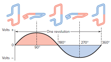
Figure 8 Generation of an AC sine wave voltage.
Electric Motors
Electric motors are used to convert electric energy into mechanical energy. Motors use magnetism and electric currents to operate. There are two basic categories of motors, AC (Figure 9) and DC. Both use the same fundamental parts but with variations to allow them to operate from two different kinds of electric power supply, alternating current or direct current.
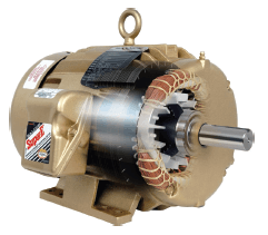
Figure 9 AC electric motor.
The operation of an electric motor depends upon the interaction of two magnetic fields. Whenever a conductor carrying current is placed in a magnetic field, it will experience a force which tends to push it out of the magnetic field. The right-hand rule for motors (Figure 10) indicates the direction that a current-carrying conductor will be moved in a magnetic field.
When the forefinger is pointed in the direction of the magnetic lines of force, and the center finger in the direction of the current flow in the conductor, the thumb will point in the direction that the conductor will move.
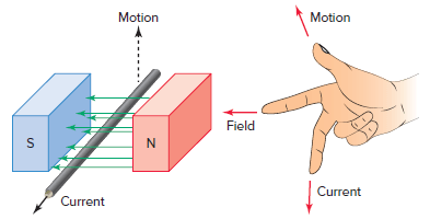
Figure 10 Current-carrying conductor in a magnetic field.
If the conductor is bent in the form of a loop, current flows in one direction on one side of the loop and in the opposite direction on the other. As a result the two sides of the coil experience forces in opposite directions, as illustrated in Figure 11. The pair of forces with equal magnitude but acting in opposite directions causes the loop to rotate around its axis, developing motor torque.
The overall turning force on the armature loop depends on several factors, including field strength and the amount of current flow through the loop. In the practical motor, if the motor does not develop enough torque to pull its load, it stalls.
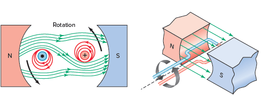
Figure 11 Developing motor torque.
Review Question
- List two advantages that electromagnets have over permanent magnets for many practical applications.
- Explain how the lift-and-drop control of a crane-operated lifting magnet is accomplished.
- Explain how solenoids operate.
- Explain how solenoid valves operate.
- In the operation of a transformer, what determines the change in voltage between the primary and secondary coils?
- Explain how an electromagnetic control relay operates.
- State the principle of operation of a generator.
- In the operation of an AC generator the output voltage varies in both voltage value and polarity.
- What causes the output voltage to vary in value?
- What causes the output voltage to vary in polarity?
- Compare the function of electric generators and motors.
- What is the basis for the operation of an electric motor?
- Describe the two methods used to create electromagnetic induction.
- When does mutual inductance between two coils occur?
- Which side of a transformer is designated as the primary and what side as the secondary?
Answers
- Electromagnets can be made much more powerful and the strength of the electromagnet can be easily controlled.
- By connection and disconnection of voltage to an electromagnet.
- Applying power to the coil produces a magnetic field that pulls or pushes the plunger into the coil.
- When the coil is energized the magnetic field created pulls the plunger upwards to open the valve permitting liquid flow from inlet to outlet. When the solenoid coil is de-energized a spring closes the valve.
- The ratio of the turns in the primary and secondary coils.
- The relay generates electromagnetic force when input voltage is applied to the coil. The electromagnetic force moves the armature that switches the contacts.
- The generator principle states that: a voltage is induced in a conductor whenever the conductor is moved through a magnetic field so as to cut lines of force.
- (a) The value of the output voltage varies in an AC generator based on the number of lines of flux that are being cut. (b) The output voltage polarity changes when direction of the coils relative to the direction of the magnetic field changes.
- An electric generator is a machine that uses magnetism to convert mechanical energy into electrical energy. Electric motors are used to convert electric energy into mechanical energy.
- Whenever a conductor carrying current is placed in a magnetic field, it will experience a force which tends to push it out of the magnetic field.
- By motion of a conductor across a magnetic field AND By motion of a conductor across a magnetic field.
- When the two coils are magnetically linked together by a common magnetic flux.
- The primary is the side connected to the AC power input and the secondary is the side connected to the output.
Electromagnets Key Takeaways
Electromagnets are crucial in a wide range of applications due to their versatility and controllable magnetic strength. Unlike permanent magnets, electromagnets can be made much stronger and their magnetic force can be adjusted easily by altering the current. This makes them indispensable in technologies like crane electromagnets for lifting heavy loads, solenoids for precise movements, and solenoid valves for controlling fluid flow. Furthermore, electromagnets are at the core of transformers, relays, electric generators, and motors, which convert electrical energy to mechanical energy and vice versa. The ability to control and manipulate the strength of electromagnets allows them to perform critical roles in industries such as manufacturing, power generation, and automation, demonstrating their importance in modern technology.