This article provides an overview of Thevenin’s Theorem, explaining how complex circuits can be simplified into an equivalent circuit with a single voltage source and series resistance. It includes solved examples and highlights practical applications for analyzing and simplifying electrical networks with varying loads.
Suppose that the circuit of Figure 1(a) is sealed in a black box (represented by the thick line) with only the terminals A and B exposed. A high-resistance voltmeter connected across these terminals shows that the open-circuit output voltage of the circuit is 80 V.
Similarly, connecting a very low resistance ammeter across terminals A and B shows that the short-circuit current is about 2.0 mA. Hence, the black box appears to have an internal resistance of
\[{R}_{Th}=\frac{{{E}_{oc}}}{{{I}_{sc}}}=\frac{80V}{2mA}=40k\Omega \]
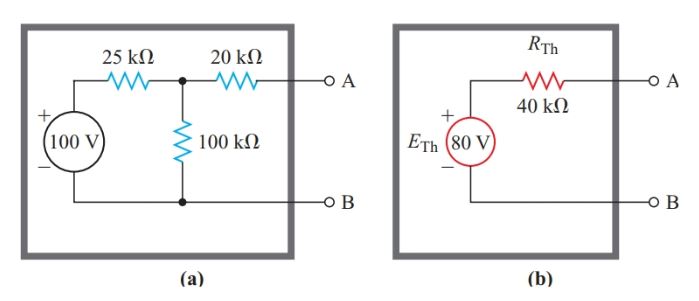
Figure 1 (a) Original voltage source; (b) Thevenin-equivalent source
As far as we can tell without opening it, the box contains an 80-V source, as shown in Figure 1(b). Any load connected to terminals A and B of the equivalent circuit of Figure 1(b) draws exactly the same current with exactly the same voltage drop as the load would if it were connected to the network of Figure 1(a).
In fact, all that we can determine from measurements at the output terminals of any network containing one or more voltage sources is that the network is equivalent to a simple constant-voltage source with a single internal resistance in series with it. The French engineer Leon Charles Thevenin (1857–1927) stated the principle of this equivalence as a theorem:
Any two-terminal network of fixed resistances and voltage sources may be replaced by a single voltage source that has
- An equivalent voltage equal to the open-circuit voltage at the terminals of the original network, and
- An internal resistance equal to the resistance looking back into the network from the two terminals with all the voltage sources replaced by their internal resistances.
We can apply Thevenin’s theorem to any of the resistance networks by treating one branch of the network as a load and the remainder of the network as a two-terminal network containing one or more voltage sources.
Having decided which branch of the original network to treat as a load, we remove it from the original network and place it in a Thevenin-equivalent circuit. Then, we apply Thevenin’s theorem to determine the rest of the equivalent circuit.
Note that Thevenin uses an “ohmmeter” approach to determine the internal resistance “looking back into” the open-circuit terminals of the source network.
Thevenin’s Equivalent Circuit Example 1
What current does a 10-kV resistor draw when it is connected to a 100-V source through the T-network shown in Figure 1(a)?
Solution
Step 1
Connect the 10-kV resistor to a Thévenin-equivalent source consisting of a constant voltage source ETh with a series internal resistance RTh, as shown in Figure 2(b).
According to Thevenin’s theorem, ETh equals the open circuit voltage between terminals A and B of Figure 1(a).
Since an open circuit draws no current, there is no voltage drop across the 20-kV resistor. Hence, the open-circuit terminal voltage is the same as the voltage drop across the 100-kV resistor.
When terminal A is open-circuit, the 25-kV and the 100-kV resistors form a simple series circuit. Then, the voltage-divider principle provides us with the voltage drop across the 100-kV resistor. This voltage drop is the open-circuit voltage between terminals A and B, which is ETh in the Thévenin-equivalent circuit.
\[{{E}_{Th}}=\frac{100}{25+100}\times 100V=80V\]
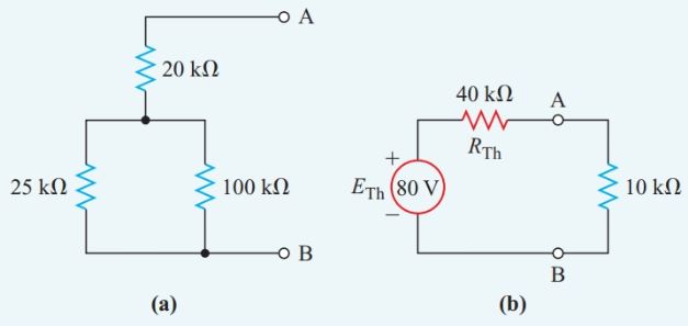
Figure 2 Thevenin’s Equivalent circuit for Step 2 of Example 1
Step 2
Replace the actual source in Figure 1(a) by its internal resistance, which is zero ohms. The original circuit of Figure 1(a) then becomes the series-parallel resistance network of Figure 2(a). The equivalent resistance for this network is
\[{{R}_{Th}}=20k\Omega +\frac{25k\Omega \times 100k\Omega }{25k\Omega +100k\Omega }=40k\Omega \]
Step 3
Solve for the current through the 10-kV resistor in the Thevenin- equivalent circuit of Figure 2(b).
\[I=\frac{{{E}_{Th}}}{{{R}_{T}}}=\frac{80V}{40k\Omega +10k\Omega }=1.6mA\]
Thevenin’s Equivalent Circuit Example 2
A resistor passing a 20-mA current is in parallel with a 5.0-kV resistor. This combination is in series with another 5.0-kV resistor, and the whole network is connected to a 500-V source. Find the resistance of the resistor that is passing the 20-mA current.
Solution
Step 1
We select the unknown resistance passing the 20-mA current as the load, remove it from the original circuit in Figure 3(a), and place it in the Thevenin- equivalent circuit of Figure 3(b).
The voltage-divider principle then gives the open-circuit terminal voltage of the remaining circuit in Figure 3(a):
\[{{E}_{Th}}=\frac{5}{5+5}\times 500V=250V\]
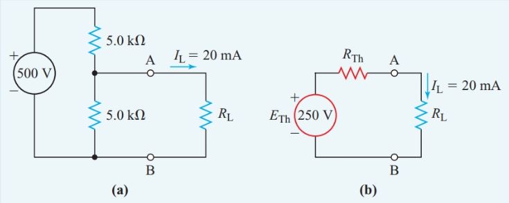
Figure 3 Circuit diagram for Step 1 of Example 2
Step 2
If we replace the original voltage source with its internal resistance of zero ohms, the circuit of Figure 3(a) becomes the simple parallel resistance network of Figure 4(a), and
\[{{R}_{Th}}=20k\Omega +\frac{5k\Omega \times 5k\Omega }{5k\Omega +5k\Omega }=2.5k\Omega \]
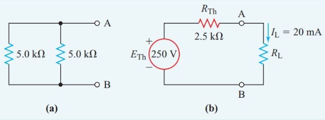
Figure 4 Thevenin’s Equivalent circuit for Step 2 of Example 2
Thevenin’s Theorem Applications
Often the load in a circuit varies while the other circuit elements are fixed. For example, various appliances may be connected to a household outlet, thus changing the load on that branch of the house wiring.
When we are analyzing a circuit that has a varying load, Thevenin’s theorem can save us some tedious calculations by letting us replace the unchanged portion of the circuit with a simple equivalent circuit, as shown in Figure 5.
However, we can apply Thevenin’s theorem only to linear components (components with values that do not vary with voltage or current).
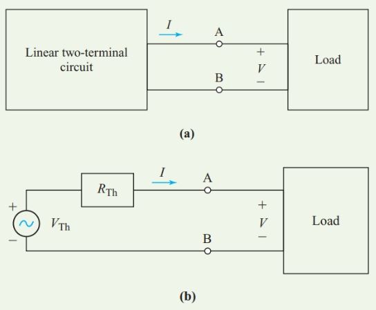
Figure 5 Thevenin’s Theorem Application
Thevenin’s Theorem Key Takeaways
Thevenin’s Theorem is a powerful tool for simplifying complex electrical circuits into a more manageable form, especially when analyzing the effect of varying loads. Its ability to reduce a network of voltage sources and resistors into a single voltage source with a series resistance makes it invaluable in practical applications like electrical load analysis, fault diagnosis, and circuit design. In real-world scenarios—such as household electrical systems, communication circuits, or industrial automation—loads frequently change while the rest of the network remains constant. Thevenin’s approach allows engineers to predict circuit behavior efficiently and accurately without recalculating the entire system each time. This not only saves time but also enhances the reliability of system analysis and design, making it an essential concept in both theoretical and applied electrical engineering.