The article discusses different types of braking methods in DC motor, primarily focusing on electric braking and dynamic braking. It explains the working principles, circuit components, and applications of these braking techniques, highlighting their effectiveness in controlling motor stopping time and ensuring smooth operation in various industrial settings.
Electric braking is a method of braking in which a DC voltage is applied to the stationary windings of an electric motor after the AC voltage is removed. Electric braking is also known as DC injection braking. See Figure 1.
Electric braking is an efficient and effective method of braking most AC motors. Electric braking provides a quick and smooth braking action on all types of loads, including high-speed and high-inertia loads.
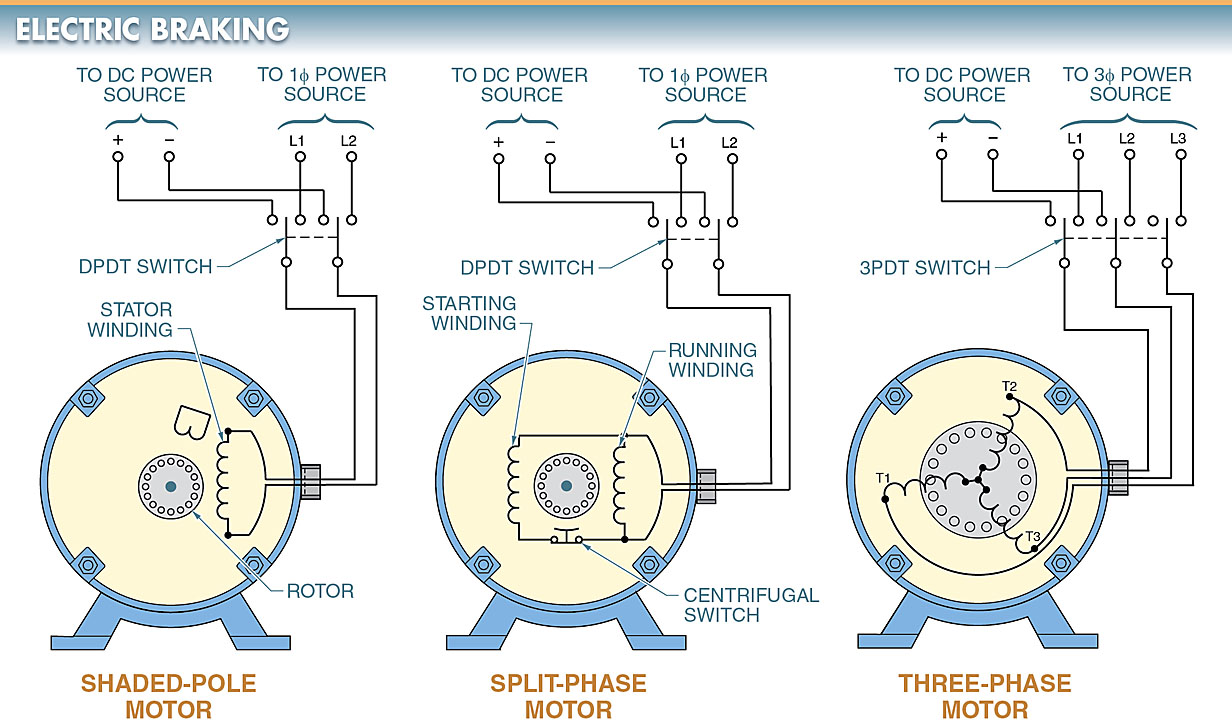
Figure 1. Electric braking is achieved by applying DC voltage to the stationary windings of an electric motor after the AC is removed.
Electric Braking Operating Principle
The principle stating that unlike magnetic poles attract each other and like magnetic poles repel each other explains why an electric motor shaft rotates. However, the method in which the magnetic fields are created changes from one type of motor to another.
In AC induction motors, the opposing magnetic fields are induced from the stator windings into the rotor windings by the transformer action. The motor continues to rotate as long as the AC voltage is applied.
The motor coasts to a standstill over a period of time when the AC voltage is removed because there is no induced field to keep it rotating.
Electric braking can be used to provide an immediate stop if the coasting time is unacceptable, particularly in an emergency situation.
Electric braking is accomplished by applying a DC voltage to the stationary windings once the AC voltage is removed. The DC voltage creates a magnetic field in the stator that does not change polarity.
The constant magnetic field in the stator creates a magnetic field in the rotor. Because the magnetic field of the stator does not change in polarity, it attempts to stop the rotor when the magnetic fields are aligned (N to S and S to N). See Figure 2.
The only force that can keep the rotor from stopping with the first alignment is the rotational inertia of the load connected to the motor shaft. However, because the braking action of the stator is present at all times, the electric motor brakes quickly and smoothly to a standstill.
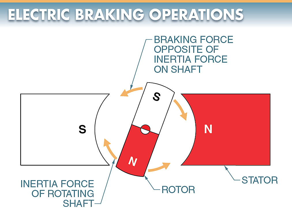
Figure 2. The DC voltage applied during electric braking creates a magnetic field in the stator that does not change polarity.
DC Electric Braking Circuit
DC is applied after the AC is removed to bring the electric motor to a stop quickly. See Figure 3. This circuit, like most DC braking circuits, uses a bridge rectifier circuit to change the AC into DC. In this circuit, a three-phase AC motor is connected to three-phase power by a magnetic motor starter.
The magnetic motor starter is controlled by a standard stop/start pushbutton station with memory. An off-delay timer is connected in parallel with the magnetic motor starter. The off-delay timer controls a NO contact that is used to apply power to the braking contactor for a short period of time after the stop pushbutton is pressed. The timing contact is adjusted to remain closed until the motor comes to a stop.
Braking Contactor
The braking contactor connects two motor leads to the DC supply. A transformer with tapped windings is used to adjust the amount of braking torque applied to the motor.
Current-limiting resistors could be used for the same purpose. This allows for a low- or high-braking action, depending on the application. The larger the applied DC voltage, the greater the braking force.
Interlock System in Electric Motor
The interlock system in the control circuit prevents the electric motor starter and braking contactor from being energized at the same time. This is required because the AC and DC power supplies must never be connected to the motor simultaneously.
Total interlocking should always be used on electrical braking circuits. Total interlocking is the use of mechanical, electrical, and pushbutton interlocking. A standard forward and reversing motor starter can be used in this circuit, as it can with most electric braking circuits.
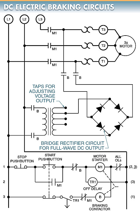
Figure 3. DC is applied after AC is removed to bring the electric motor to a stop quickly.
Dynamic Braking in DC Motors
Dynamic braking is a method of an electric motor braking in which a motor is reconnected to act as a generator immediately after it is turned off.
Connecting the motor in this way makes the motor act as a loaded generator that develops a retarding torque, which rapidly stops the motor.
The generator action converts the mechanical energy of rotation to electrical energy that can be dissipated as heat in a resistor with a high-power rating. See Figure 4.
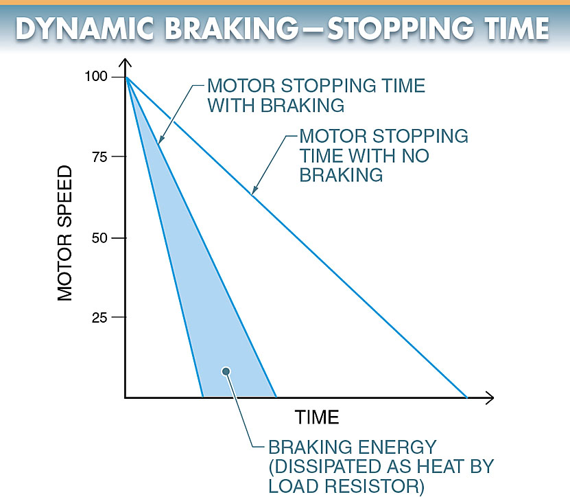
Figure 4. Dynamic braking significantly reduces electric motor stopping time when a motor is reconnected to act as a generator immediately after it is turned off.
Dynamic braking is normally applied to DC motors because there must be access to the armature via the brushes to take advantage of the generator action. Access is accomplished through the brushes on DC motors. See Figure 5.
Dynamic braking of a DC motor may be needed because DC motors are often used for lifting and moving heavy loads that may be difficult to stop.
In this circuit, the armature terminals of the DC motor are disconnected from the power supply and immediately connected across a resistor that acts as a load. The smaller the resistance of the resistor, the greater the rate of energy dissipation, and the faster the motor comes to rest.
The field windings of the DC motor are left connected to the power supply. The armature generates a counter electromotive force (CEMF). The CEMF causes current to flow through the resistor and armature.
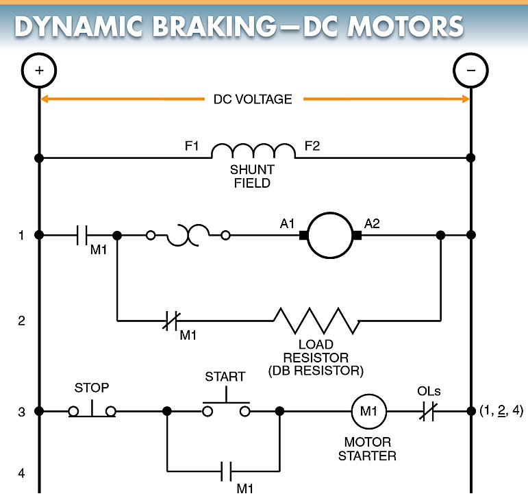
Figure 5. Dynamic braking is normally applied to DC motors because there must be access to the armature via the brushes to take advantage of the generator action.
The current causes heat to be dissipated in the resistor in the form of electrical watts. This removes energy from the system and slows the motor rotation.
The generated CEMF decreases as the speed of the motor decreases. As the motor speed approaches 0 rpm, the generated voltage also approaches 0 V.
The braking action lessens as the speed of the electric motor decreases. As a result, a motor cannot be braked to a complete stop using dynamic braking. Dynamic braking also cannot hold a load once it is stopped because there is no braking action.
Electromechanical friction brakes are often used along with dynamic braking in applications that require the load to be held.
A combination of dynamic braking and friction braking can also be used in applications where a large, heavy load is to be stopped. In these applications, the force of the load wears the friction brake shoes excessively; so then dynamic braking can be used to slow the load before the friction brakes are applied. This is similar to using a parachute to slow a racecar before applying the brakes.
Dynamic Braking Electric Motor Drives
An electric motor drive can control the time it takes for a motor to stop. The stopping time is programmed by setting the deceleration parameter.
The deceleration parameter can be set for one second (or less) to several minutes. However, for fast stops (especially with high inertia loads), a braking resistor is added. See Figure 6.
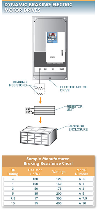
Figure 6. A braking resistor can be added to a motor drive to control fast stops on high-inertia load
Braking Resistor for DC Motor
The braking resistor also helps control electric motor torque during repeated on/off motorcycling. The size (wattage rating) and resistance (in ohms) of the braking resistor are typically selected using the drive manufacturer braking resistor chart.
The resistor wattage must be high enough to dissipate the heat delivered at the resistor. The resistor resistance value must be low enough to allow current flow at a level high enough to convert the current to heat, but not so low as to cause excessive current flow. The braking resistor(s) can be housed in an enclosure such as a NEMA Type 1 enclosure.
Types of Braking in DC Motor Key Takeaways
Both electric braking and dynamic braking play crucial roles in controlling the stopping time and operational efficiency of DC motor in various applications. These braking methods ensure safety, improve precision, and enhance performance in industrial settings where quick and controlled stopping is essential. Electric braking provides a smooth and immediate stop, making it ideal for emergency situations, while dynamic braking efficiently dissipates energy, preventing excessive wear on mechanical components. By implementing these braking techniques, industries can optimize motor control, reduce downtime, and enhance the reliability of their machinery, making them indispensable in modern automation and manufacturing processes.