An inductor is a coil of wire having resistance and, if an iron core is used, eddy current and hysteresis losses are produced when an ac current is applied.
For example, a 40ΩW fluorescent-lamp ballast typically has a resistance of 36 Ω, draws 0.4 A and consumes 10 W. The power loss due to the resistance of the windings is called copper loss:
\[P={{I}^{2}}R=0.4\times 0.4\times 36=5.76W\]
The remaining 4.24 W loss is due to eddy currents and hysteresis in the iron core, and is known as an iron loss because the losses occur in the iron core. The total losses in the inductor are equal to the sum of the copper and iron losses.
Since practical inductors do consume some power, they must consist of both pure inductance and pure resistance.
Power in AC Circuits
A purely resistive load consumes power, while a purely inductive load consumes no power. When resistance and inductance are combined in one circuit, there will be a value of power consumed that is dependent on the resistance, or resistive load, in the AC circuit.
Figure 1 shows the waveforms for voltage, current and power in a series R–L circuit where I lags V by 45°.
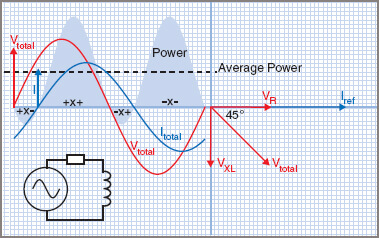
Figure 1 Power in an ac R–L circuit
It can be seen that there is more positive than negative power, so the resultant or average power will be positive. It will be a lesser value than for a purely resistive value load, but greater than that for a purely inductive load.
True Power (P)
The applied voltage is split into two components at right angles to each other, as shown in Figure 1 in the phasor diagram. VR is in phase with the current, while VL is leading the current by 90° and is shown at 90° to VR.
Previously it was stated that, in a purely AC resistive circuit, V and I are in phase and the power consumed is found from P = V.I. This is still true as long as the resistive or in-phase component of voltage is used. That is,
$P={{V}_{R}}I$
The ratio VR/Vtotal is equal to the cosine of the angle of lag Φ and it is normal to express the power consumed in terms of the line voltage V. That is:
\[\begin{align}& {}^{{{V}_{R}}}/{}_{V}=\cos \phi \\& {{V}_{R}}=V\cos \phi \\\end{align}\]
Since
\[\begin{align}& P={{V}_{R}}I \\& \text{then also} \\& P=V\cos \phi I \\\end{align}\]
that is,
$P=VI\cos \phi $
In electrical power work, which mainly deals with sinusoidal waveforms, the term ‘cos Φ’ is called the power factor or PF. This expression is in common use.
Apparent Power (S)
For AC circuits that have both resistance and reactance, the product of the measured line voltage and line current produces a value greater than the power consumed, which therefore cannot be expressed in watts. The value is known as the apparent power, which is still useful in dealing with electric machinery, as you will soon learn.
Apparent power is measured in units known as volt-amperes (VA). Many ac machines, particularly alternators and transformers, are rated in VA to give an indication of both core and iron size and the current rating of the windings, which you should notice is greater than the current required for the power consumed. For example, an alternator could be rated at 100 kVA yet only deliver 80 kW:
$S=VI$
Reactive Power (Q)
Reactive power is found from the product of the line voltage and the reactive proportion of the line current that does not consume power.
A capacitor exhibits only reactive power, because the current flowing is leading the voltage by 90° and the true power is zero. Reactive power is sometimes called ‘wattles power’ for this reason and is measured in volt-amperes reactive, abbreviated VAR:
$Q=VI\sin \phi $
Power Triangle
True power, apparent power and reactive power can be represented by a power triangle, as shown in Figure 2.
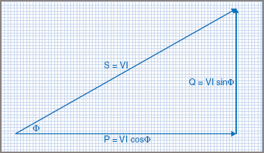
Figure 2 Power Triangle
True power equals the apparent power in volt-amperes multiplied by the power factor of the circuit. If cos Φ is calculated from 0° to 90°, the power factor will be seen to vary from 1 for a purely AC resistive circuit to 0 for a purely reactive circuit, which means that the power factor can only vary from 1 to 0, with PF = 1 being an AC resistive circuit and PF = 0 being a pure reactive circuit.
Similarly, if sin θ is calculated from 0° to 90°, the reactive power ratio will be seen to vary from 0 for a purely AC resistive circuit to 1 for a purely reactive circuit.
Power Factor (PF) in AC Circuit
The power factor is the factor or ratio by which apparent power is multiplied to obtain the true power, or the actual power being consumed.
For all electrical power work with sinusoidal waveforms:
\[Power\text{ }Factor=\cos \theta ={}^{R}/{}_{Z}\]
The relationship between true power and apparent power can also lead to obtaining a value for the power factor:
Power factor (PF) = cos θ = true power/apparent power
$PF=\cos \theta ={}^{P}/{}_{S}$
Effects of Low Power Factor
In broad general terms, the lower the value of the power factor, the greater will be the current required to supply the same true power. Because of the extra current flowing, other factors are involved:
| 1. | larger cross-sectional area conductors required |
| 2. | larger transformers |
| 3. | higher-rated switch gear |
| 4. | fuses of a higher current rating |
| 5. | higher voltage drops along conductors |
| 6. | extra copper losses |
| 7. | decreased efficiency – higher losses, more fuel |
| 8. | Higher generating and capital costs. |
Due to the effects of a low power factor, the method of rating electrical equipment by power consumption is not always satisfactory. Some electrical equipment is rated by the volt-ampere (VA) rating method. The voltage determines the insulation required and the current determines the size of the conductors.
For example, Figure 3 describes a transformer designed for 250 V and 40 A. The rating of this transformer is 250 × 40 = 10000 VA = 10 kVA.
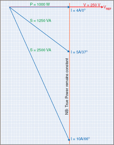
Figure 3 Power factor effect on current
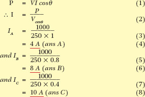
Example 1
If a 1 kW load is connected to a 250 V ac supply, find the current flowing at:
| (a) | unity power factor (θ = 0°) |
| (b) | power factor = 0.8 (θ = 37°) |
| (c) | power factor = 0.4 (θ = 66°). |
If it were used to supply an electric furnace which has a unity power factor (PF = 1), it could supply a maximum of 10000 × 1 = 10 kW of power. If the same transformer were used to supply a load at 0.8 power factor, the maximum power it could supply would be 10000 × 0.8 = 8 kW. When a transformer, or any electrical equipment, is rated in VA, a value is given that is independent of the power factor of the load.
Causes of Low Power Factor
In practice, many AC circuits are inductive and as a result cause currents to lag. An AC circuit with a leading current (i.e. a capacitive circuit) is seldom found, although the effect does tend to occur in long-distance transmission lines.
The major causes of a low power factor are lightly loaded electric motors and transformers, and fluorescent lighting circuits. Motors and transformers should be designed to run at or near full load.
For fluorescent lighting circuits using ballasts, capacitors are added to the AC circuit to improve the power factor. Modern electronic ballast types are designed to produce a PF nearer to unity.
Electricity generating authorities, under their conditions of supply, usually stipulate conditions for the use of equipment at poor power factor values.
Determining Power Factor
The power factor of an AC circuit can be obtained by using a voltmeter, ammeter and wattmeter. Figure 4 shows the circuit for measuring the power factor of a single-phase ac motor.
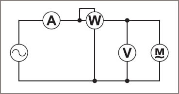
Figure 4 Power factor measurement
The power factor can then be found from:
\[PF={}^{P}/{}_{S}={}^{Watts}/{}_{Volt-Amperes}\]
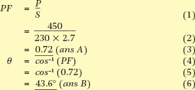
Power Factor Example 2
A single-phase motor draws 2.7 A on 230 V and a wattmeter in the circuit reads 450 W. Find the power factor and phase angle.
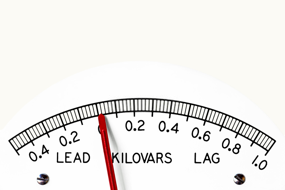
The power factor can also be measured by using a power factor meter (cos θ), as shown in Figure 5. The meter is connected in the same manner as a wattmeter and the scale is calibrated in values of power factor.
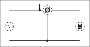
Figure 5 Power factor meter
Calculation
In a series circuit, the power factor can be obtained by using the values of resistance and impedance.
Phasor Diagrams
Another method of obtaining the power factor is by drawing a phasor diagram to scale, measuring the phase angle and then using a calculator to find the cosine of the angle.
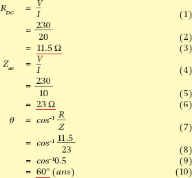
Example 3
An inductor draws 20 A on 230 V DC and 10 A on 230 V ac. Calculate the angle of lag when on ac.
Power Factor Correction
For economic reasons, the recommended value of the power factor is 0.8. Below 0.8 the current increases rapidly, whereas above 0.8 the cost of the equipment necessary to correct the power factor is too great when compared with the overall benefit gained (see Figure 6).
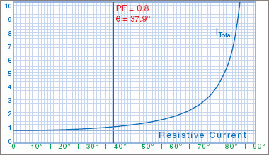
Figure 6 Power factor versus total current
Reduced power factor, perhaps due to oversize motors operating at less than full load, causes a sharp rise in current, as shown in Figure 5, where the total current is plotted against the phase angle from the resistive current to 10 times the resistive current at around 85° or a PF of 0.1.
To correct the power factor, it is necessary to reduce the phase angle between the line current and voltage, without affecting the values of voltage or load current.
Most low power factor problems are caused by inductive loads, such as induction motors and transformers.
One method used to improve the power factor in this type of AC circuit is to connect a capacitor in parallel with the load, as shown in Figure 7 with the effects shown in Figure 8.
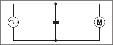
Figure 7 Motor with PF correction
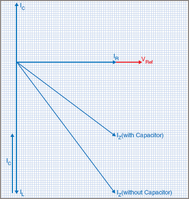
Figure 8 PF correction phasor diagram
In this way, IL remains the same and each load operates at its own power factor, but the overall power factor of the combined circuit is improved. A pure capacitor is a load that operates at a leading zero power factor and, when connected across an inductive load, tends to oppose the lagging effect of the inductance–but without consuming any power.
For example, a 230 V single-phase installation supplies a number of motors requiring 10 kW of power. On single phase, this results in a load current of 43.5 A. If the power factor of the load is 0.6 (cos 53°), the total current in the line will be 72.5 A. Correcting the PF to 0.8 (cos 37°) would reduce the current to 54.5 A, a decrease of ∼20 per cent for the same true power. This illustrates the need for improving the power factor.
Power Factor Example 4
A single-phase 230 V 50 Hz induction motor draws 15 A at 0.6 power factor. Determine the line current and power factor when an 80 μF capacitor is connected across the line.
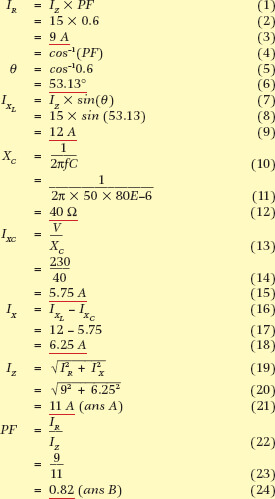
Points to note in this example are:
| 1. | Although an extra component (the capacitor) has been added, the line current has been reduced, while the in-phase or power component of current (OA) has retained its original value. |
| 2. | The motor current and power factor remain unaltered. |
| 3. | The power factor of the resultant combined load has been improved. |
| 4. | The power consumption remains at its original value. |
| 5. | The volt-ampere rating of the combined circuit has been reduced. |
| 6. | The reactive power rating of the combined circuit has been reduced. |
The purpose of using capacitors to improve the power factor is to provide a leading current to counteract the lagging current drawn by the load, and at the same time not increase the value of power consumed. Supply authorities try to keep as high a value of power factor as is economically possible in their supply systems. They do this by regulating the minimum allowable value of power factor for any load connected to the supply, and accordingly there is regular demand for power factor correction capacitors.
Power factor improvement using a capacitor can be calculated as shown in Example 4. However, in that example, the power factor using the suggested capacitor still did not improve the power factor above the 0.8 usually required by supply authorities. A 100 μF capacitor might give an acceptable PF value, but that would simply be another guess.
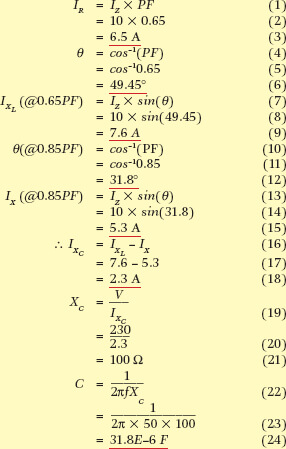
A better method would be to calculate the value of capacitance required to improve the overall power factor to an acceptable value. Example 5 shows a method of calculating the capacitance required to improve a known PF to a specified value. In this case a PF of 0.85 was chosen to ensure that the improved PF is better than 0.8.
A 31.8 μF capacitor would have to be specially made at a very high cost. In this case, a 32 µF capacitor would do the job with a little to spare. In practice, this might be made up of four 8 μF capacitors in parallel, or perhaps a 35 μF capacitor if that value is available.
Power factor correction is sometimes dealt with by using the reactive power approach. The value of current flowing in the capacitor, multiplied by the voltage across it, gives the reactive power or VAR value.
For example, in Example 5, the motor took 230 V at 10 A or 2.3 kVA. The true power is found from P = VI(PF) or 230 × 10 × 0.65 = 1.495 kW. If the power factor is improved to 0.85, then the true power will remain the same but the kVA will be reduced, and therefore the line current will be reduced.
If P = VI cos θ for either PF values, then it follows that:
\[V{{I}_{1}}\left( P{{F}_{1}} \right)=V{{I}_{2}}\left( P{{F}_{2}} \right)\]
The voltage is the same each time and so cancels out, leaving us with a formula for the improved line current:
\[{{I}_{2}}={{I}_{1}}\times \left( {}^{P{{F}_{1}}}/{}_{P{{F}_{2}}} \right)=10\times {}^{0.65}/{}_{0.85}=7.647A\]
Capacitor Calculation for Power Factor Correction Example 5
A motor takes a current of 10 A at 0.65 power factor, lagging, from a 230 V 50 Hz supply. What size of capacitor is required to improve the power factor to 0.85 lagging?
Which tells us how much the current will improve at the specified new power factor:
\[{{I}_{2}}={{I}_{1}}\times \left( {}^{P{{F}_{1}}}/{}_{P{{F}_{2}}} \right)\]
The reactive power is calculated from Q = VI sin θ and θ is cos−1(PF) so reactive power can also be found from Q = VI sin(cos−1(PF)). Through some trigonometry, this can be simplified to:
\[Q=VI\sqrt{1-P{{F}^{2}}}\]
Therefore at 0.65 PF and 10 A:
\[Q=230\times 10\times \sin \left( {{\cos }^{-1}}\left( 0.65 \right) \right)=1747VAR\]
And at 0.85 PF and 7.647 A:
\[Q=230\times 7.647\times \sin \left( {{\cos }^{-1}}\left( 0.85 \right) \right)=927VAR\]
Therefore the reactive power needed to make that improvement is 1747 − 927 = 821 var of capacitive load, or leading reactive power.
That means a capacitive current of I = VAR/V = 821/230 = 3.57 A in parallel with the load current.
Power Factor Correction Example 6
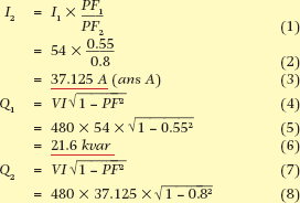
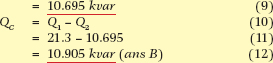
A 480 V single-phase supply feeds an installation that draws 54 A at a power factor of 0.55. What will the current be if the power factor is improved to 0.8? Determine the kVAR rating of the capacitor required to improve the power factor to 0.8.
Where the values of reactive power required are economically beyond the range of available capacitors, another means of power factor correction is required.
A type of motor called a synchronous motor has the characteristic, under certain conditions, of drawing a leading current. Synchronous motors are usually installed in large industrial premises and used to drive air compressors or other similar machines where a constant service is required throughout the plant. While providing the service, the motor also provides a leading current to correct or improve the power factor of the whole factory.
For installations requiring 20 Mvar (20 Mega var) or more of power factor correction, the synchronous motor is often installed without a load connected to it, and it is then usually called a synchronous capacitor or condenser.
