The most common generator used in production of electrical power is the three-phase generator. It consists of a rotating magnetic field inside three sets of windings. See Figure 1, part A. The three sets of windings are referred to as the armature of the generator. The armature provides power for the load circuit. In this case the generator has a stationary armature and a rotating magnetic field. See Figure 1, part B.
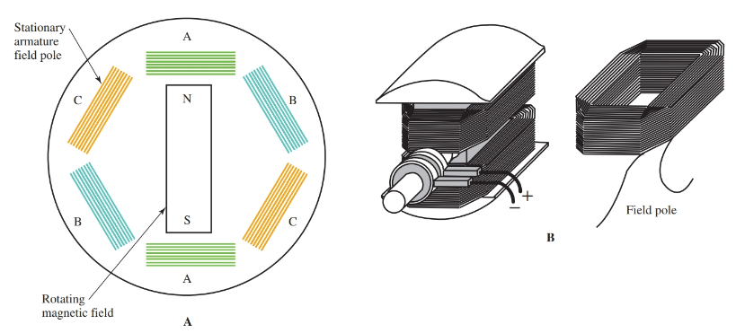
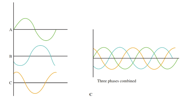
Figure 1. A—As the magnetic field rotates inside the generator housing, a three-phase electrical output develops. B—The rotating field inside the stationary armature ac generator consists of coils formed and connected to slip rings. The fields are powerful electromagnets. C—Each phase has the same voltage peak and frequency. The peak positive polarity occurs 120 electrical degrees apart.
Look again at Figure 1, part A. The sine wave that develops from three-phase electrical systems is unique. The three windings of the armature are connected as pairs. They are called phase A, phase B, and phase C. As the magnetic field rotates inside the generator armature windings, three different sine waves develop. The three waves are 120 electrical degrees apart. See Figure 1, part C.
It is important to note that each of the three phases develops the same frequency and same peak voltage. The difference between the three phases is that each phase develops positive and negative voltage peaks at different times, making each phase unique.
The coils of the three-phase generator can be connected in series or parallel. When connected in series it is called a delta connection. When connected in parallel, it is called a wye or star connection. The reasons for their names can be seen in Figure 2.
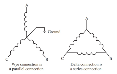
Figure 2. Generator windings are connected as either delta or wye.
You may have heard the terms 120/240 volt and 120/208 volt and wondered which is correct. Both terms are correct. The voltage present is determined by the type of generator connection used. A wye connection provides 120/208 volts, and delta connection provides 240 volts with no common, or neutral, connection.
Delta is used mainly for heavy industrial loads, while the wye connection is used to support both power and lighting circuits. While some equipment will operate on either voltage, it is best to connect a piece of machinery to the voltage level specified in its operator’s manual.
Paralleling Generators
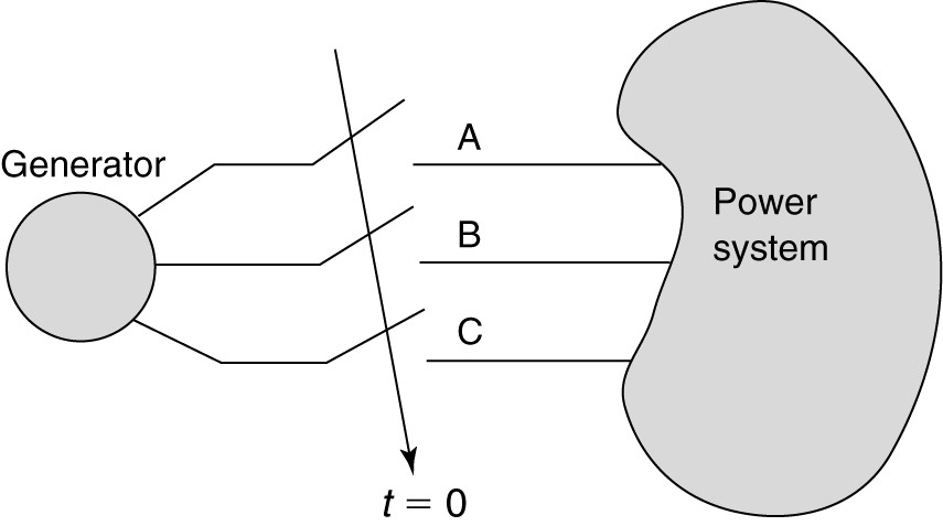
When generators are connected in parallel, three electrical characteristics of each generator must match. These characteristics are the generator’s frequency, voltage, and instantaneous polarity. If all three items do not match, and the switch is closed to connect the two generators, an electrical fire and explosion are likely to occur.
If the voltages of two parallel generators do not match, they can be made to match by adjusting one of the field pole rheostats. A slightly trickier part in paralleling generators is matching the correct frequencies of the two generators. The frequency or hertz of each generator can be compared using a frequency meter. If the frequencies do not match, we need to speed up or slow down one of the generators until they match.
Figure 3 shows sine waves of matching and non-matching instantaneous polarity. Each generator is producing a 120-volt output at 60 Hz. However, in the waves shown on the top, the third requirement, instantaneous polarity, does not match. The two sine waves in the figure are slightly off. Notice how their peaks do not align on the time axis.
The instantaneous polarity of the ac generators refers to that part of the sine wave that is rep- resented at the output terminals of each generator at that instant of time. These outputs could both be positive, or one positive and one negative. Ideally, if both sine wave patterns match, the generators have identical instantaneous polarity. These generators can be connected together electrically.
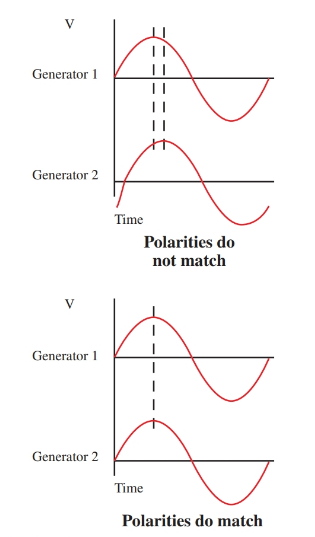
Figure 3. The two generators outputs shown on the top have the same voltage peaks and the same frequency, but their instantaneous polarities do not match. Notice how their peaks come at different times. The two outputs on the bottom match.
A simple way to tell if two three-phase generator outputs match is called the “two dark–one light method.”
Two lights are connected across the phase A and B out- puts of both generators in such a way that they match in polarity, voltage, and frequency. Both lamps should not light since there would be no difference in potential across the lamps. Another lamp is connected across two out of phase phases of the generator. This lamp should light, indicating that the two phases are out of phase with each other. See Figure 4.
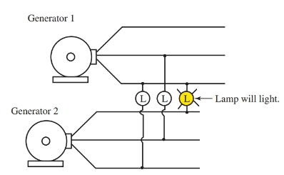
Figure 4. The two dark–one light method of paralleling generators. The two lamps connected across in phase lines from the two generators remain dark. The third lamp is connected across two out of phase lines. This lamp will glow. These two generators can be connected in parallel safely.
Troubleshooting Generators
Generators generally fail due to one of three things:
- Excessive brush wear.
- Excessive bearing wear.
- Electrical overload.
Excessive brush wear
As the brushes wear down, more arcing is produced between the brushes and commutator segments or slip rings. Excessive wear will damage the surface of either the commutator segments or the slip rings. A bluish burn pattern will be evident.
Excessive brush wear can be determined by physical inspection. The measurement for minimum brush length for a generator can be found in the owner’s manual. The brushes should be replaced if excessive wear is found. Brushes should be dressed when being replaced.
Dressing brushes refers to shaping the end of the brush to match the surface of the commutator or slip ring. A fine grade of sandpaper or emery cloth can be used for this purpose.
The sandpaper is placed between the brush and commutator with the rough side facing the brush. Rotating the commutator causes the end of the brush to wear down to match the shape of the surface it is riding against. See Figure 5.

Figure 5. The brushes of a dc motor or generator need to be shaped to match the contour of the commutator surface.
Excessive bearing wear
Worn bearings will cause a roaring sound. Excessive vibration can also be present. Another sign of excessive bearing wear is a shiny spot appearing on the armature. This spot is caused by the armature rubbing against a pole piece as the bearing wears out.
Bearings should be lubricated on a regular schedule as indicated in the owner’s manual. Some bearings are permanently sealed and require no lubrication. If brushes and bearings are properly maintained, an electrical generator can easily provide more than 20 years of service.
Electrical overload
Another cause of failure is electrical overload. Electrical overload causes the electrical insulation to break down, resulting in a short circuit or ground condition. Most times the damage can be detected by the naked eye.
A dark discoloration is a sign of excessive overload on a conductor. Test instruments are needed to determine if the armature or field windings are good or bad. Usually a voltage equal to the generator voltage is used to check the windings for grounds. Most multimeters only use a 9-volt battery and cannot detect a ground created when 120 or 240 volts are present during generator operation.
Heat from an excessive overload can also cause the generator pole pieces to lose their residual magnetism. This is very damaging to the self-excited generator. If the residual magnetism is lost, the generator will fail to build up sufficient voltage. Residual magnetism can be restored by connecting a separate dc power supply, such as a battery, to the field windings.
LESSON IN SAFETY
Before connecting the separate dc power supply to the field windings, the armature leads must be disconnected to prevent the generator from rotating. When voltage is applied to a generator, it will revolve as a motor.
