Series and parallel circuits are two basic arrangements of the source and loads. Series and parallel circuits are often combined to form complex circuits that can be understood on the basis of simpler series and parallel arrangements.
Series Circuits
A series connection is one with a single path. A series circuit has a single complete path (forming a string) from the voltage source through the load (or loads) and back. A series circuit can always be identified by the fact that it has only one current path.
Figure 1 shows three resistive loads (R1, R2, and R3) in series with a dc voltage source. All three circuits are electrically the same, but they have been drawn differently. Of course, there are other ways of drawing these three load resistances in series. The important point to remember with a series connection is that only one current path exists from the source through the loads and back to the source.
In a series circuit, the current is the same throughout the circuit.
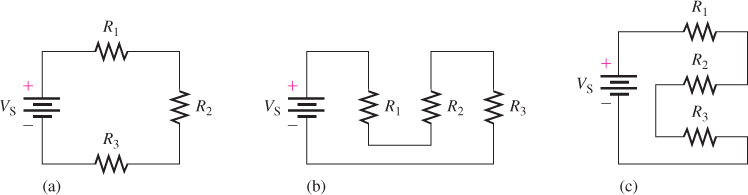
Figure 1: Series Resistive Circuit Drawn Three Ways. All three resistive loads are equivalent electrically. The standard schematic symbol for a dc source is used in each circuit.
A good analogy can be made with plumbing, where water running through a single pipe with several valves is the same through each of the valves. If one or more valves are closed, there is no water through any of them. If all the valves are completely or partially open, the same amount of water flows through all of them.
When two or more resistive loads are connected together in series, the total load resistance is the sum of the individual load resistances. The total resistance (RT) of a series circuit is the sum of the individual resistances.
\[{{R}_{T}}={{R}_{1}}+{{R}_{2}}+{{R}_{3}}+\ldots +{{R}_{n}}\]
Where Rn is the resistance of the last resistor.
Voltage Sources in Series
When several voltage sources such as batteries or solar cells are connected in series, the total output voltage is the sum of the individual voltages.
\[{{V}_{OUT}}={{V}_{1}}+{{V}_{2}}+{{V}_{3}}+\ldots +{{V}_{n}}\]
For example, four 12 V batteries connected in series produces 48 V. Figure 2 illustrates a series connection of batteries and a series connection of photovoltaic cells (solar cells).
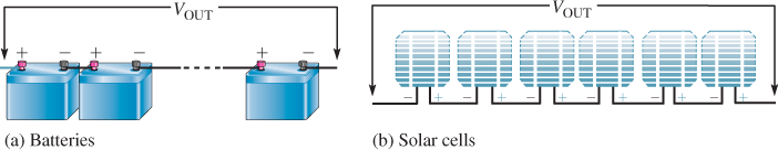
Figure 2: Examples of Series Voltage Sources
Parallel Circuits
A parallel connection is one in which two or more components are connected across the same two points (called nodes).
A parallel circuit has two or more loads connected across a common voltage source. Each load provides a separate path for current. When two or more loads are connected in parallel, the total load resistance is less than the value of the smallest-value load resistor.
With a parallel circuit, you can always trace a complete path from the voltage source to any load and back to the voltage source without going through another load. That is, the voltage source has two or more paths for current.
Figure 3 shows examples of parallel circuits. Figure 3(a) shows two resistive loads connected across a dc source. The current from the source divides between R1 and R2 Figure 3(b) shows four resistive loads across a dc source. The current from the source divides among R1, R2, R3, and R4, Figure 3(c) shows two resistive loads across a dc source, and Figure 3(d) is two resistive loads across an ac source.
Ideally, there is no limit to the number of resistive loads that can be in a parallel circuit, but in practice, there is a limit to how much current a source can provide. Notice that in each circuit, the voltage source is connected directly across two or more components. The current divides among the parallel paths in inverse proportion to the resistor value. The lowest-value resistor has the most current and the highest-value resistor has the least. If all the resistors are the same, there is an equal amount of current in each.
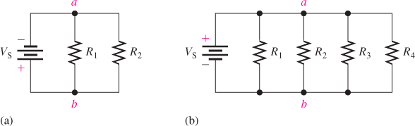
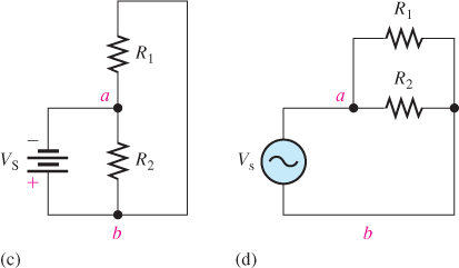
Figure 3: Four Examples of Parallel Circuits
The total resistance (RT) of a parallel circuit is reciprocal of the sum of the reciprocals of the individual resistances and is always less than the smallest-value resistor. The reciprocal of R is 1/R
\[{{R}_{T}}=\frac{1}{{}^{1}/{}_{{{R}_{1}}}+{}^{1}/{}_{{{R}_{2}}}+{}^{1}/{}_{{{R}_{3}}}+\cdots +{}^{1}/{}_{{{R}_{n}}}}\]
Where Rn is the resistance of the last resistor.
Voltage Sources in Parallel
When several voltage sources, such as batteries or solar cells, are connected in parallel, the total voltage is the same as a single battery or solar cell. However, the capacity for producing current to a load increases. For example, when four batteries are in parallel, they can produce four times as much current as a single battery to the same load. Figure 4 illustrates a parallel connection of batteries and a parallel connection of solar (photovoltaic) cells.
When a load is connected across the output of a circuit with parallel voltage sources, the total current through the load is still determined by Ohm’s law; however, each battery needs to supply only part of the total current. As a result, battery life can be extended because each battery has a less current drain.
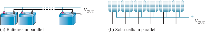
Figure 4: Examples of Parallel Voltage Sources
EXAMPLE 1
What is the total resistance of the following series resistors: 10 Ω, 15 Ω, 33 Ω and 100 Ω?
Solution
\[{{R}_{T}}=10\Omega +15\Omega +33\Omega +100\Omega =158\Omega \]
Determine the total voltage produced by 100 solar cells connected in series if each solar cell generates 0.5 V.
Solution
Because all of the solar cells produce the same voltage, simply multiply as follows. This is equivalent to adding 0.5 V one hundred times.
\[{{V}_{T}}=100(0.5V)=50V\]
Find the total resistance of the resistors in part (a) if they are all connected in parallel.
Solution
\[{{R}_{T}}=1/(1/10\Omega +1/15\Omega +1/33\Omega +1/100\Omega )\]
\[=1/(0.100+0.067+0.030+0.010)=1/0.207=4.83\Omega \]
Determine the currents in the smallest and the largest resistors in part (a) if they are connected to the solar cells in part (b).
Solution
The 10 Ω resistor has the most current, which is, by Ohm’s law:
\[I=V/R=50V/10\Omega =5A\]
The 100 Ω resistor has the least current, which is, by Ohm’s law:
\[I=V/R=50V/100\Omega =0.5A\]
Review Question
- What is a series circuit?
- Three resistors, a 10 Ω, a 4.7 Ω and an 8.2 Ω are connected in series with a 12 V source that is producing 0.524 A of current. What is the current in each of the resistors?
- What is a parallel circuit?
- Four resistors having different values are connected in parallel with a voltage source. Which resistor has the most current?
- How would you connect four 12 V batteries to get more voltage? More current capacity?
Answers
- A series circuit is one with one path for current.
- 0.524 A
- A parallel circuit is one with two or more paths for current.
- The smallest value resistor has the largest current.
- To get more voltage, connect the batteries in series; to increase current capacity, connect them in parallel.
Series and Parallel Circuits Key Takeaways
Understanding series and parallel circuits is essential for designing, analyzing, and troubleshooting electrical and electronic systems. These fundamental arrangements form the building blocks of more complex circuits used in real-world applications. Series circuits are crucial where consistent current is needed across components, such as in string lights or battery chains, while parallel circuits are widely used in household wiring and electronic devices, allowing independent operation of components and improved current distribution.